Publications
AS1684:2021 Parts 2 and 3
AS1684:2021 Parts 2 and 3
Based in WoodSolutions AS 1684 User Guide 1, 2012. All references have been updated to the 2021 version of AS 1684
AS 1684 Parts 2 and 3 provide nominal and (where required) specific fixing details for various wind classifications. Some confusion has arisen, as to if specific fixings are required, what nominal fixings are required in addition to the specific fixings. The key to this issue is given in Clause 9.6.1, first paragraph, second sentence that states: "Where specific tie-down fixings provide equal or better resistance to gravity or shear loads, then nominal nailing is not required in addition to the specific tie-down fixing".
The intent of this requirement is to ensure that even if specific fixings are required to resist uplift forces (tie-down connections), that other forces and actions due to gravity, shear and construction loads are not overlooked.
A strap over a rafter may be required for tie-down of roof uplift forces, but this alone does not provide shear resistance to lateral wind pressure that acts on the side of the wall. The nominal nailing requirements (usually 2 skew nails through the rafter into the top plate) can however resist this lateral load.
For some other situations, the addition of the minimum nominal nailing requirements would be redundant because the specific tie-down fixings provide far greater capacity to handle the other forces and actions(other than uplift).
There are no nominal connections specified for roof battens to rafters/trusses, but specific tie-down is required (nails, screws, etc). The last sentence of the first paragraph in Clause 9.5 states that: "Unless otherwise specified herein, not less than two nails shall be provided at each joint." As a minimum, battens are nailed by one nail to rafters/trusses. This is still the minimum requirement even when a specific fixing is required and obviously the "catch all" minimum 'two nail' rule is excessive for roof battens.
On the other hand, if we consider another specific batten tie-down that may be required such as a strap over the batten, the detail shown in Table 9.25 (f) and (g) does not indicate the need for an additional nail. It is obvious in this case that for construction purposes alone, at least one nail should fix the batten to the rafter/truss prior to the fixing of the strap.
Let commonsense prevail! If the first fixing used to connect one member to another is a specific fixing, and it also caters for construction, and gravity loads, then the additional nominal nailing requirements are not required.
Based in WoodSolutions AS 1684 User Guide 2, 2012. All references have been updated to the 2021 version of AS 1684
AS 1684 Parts 2 and 3 requires temporary bracing to be installed to provide stability to the house so that it can resist wind and construction loads during construction. Lateral forces on the building during construction can be as high or higher than the forces on a completed clad house.
These lateral forces can arise from construction loads such as unevenly stacked materials on the floor or roof frame or from wind creating 'drag' forces on individual framing members or, a combination of both.
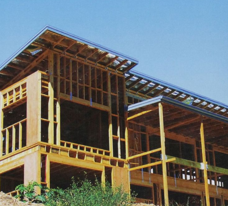
The most vulnerable time during construction is when the roof is clad but the walls still have no external or internal sheeting or lining installed.
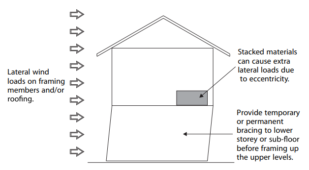
Figure 1: Lateral loads acting on a building during its most vulnerable condition
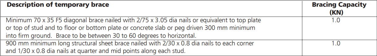
AS 1684 only requires temporary bracing to be 60% of the permanent bracing and this reflects the lower probability of a building being subjected to its long term maximum design gust wind speed event, during the relatively short period of construction.
Temporary bracing can be achieved by:
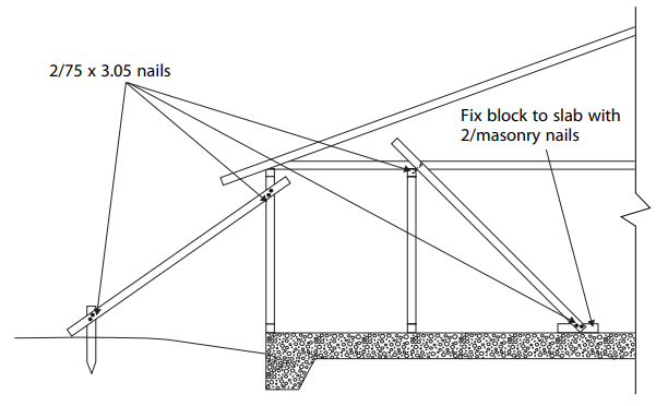
Figure 2: Temporary diagonals ensuring stability
Based in WoodSolutions AS 1684 User Guide 3, 2012. All references have been updated to the 2021 version of AS 1684
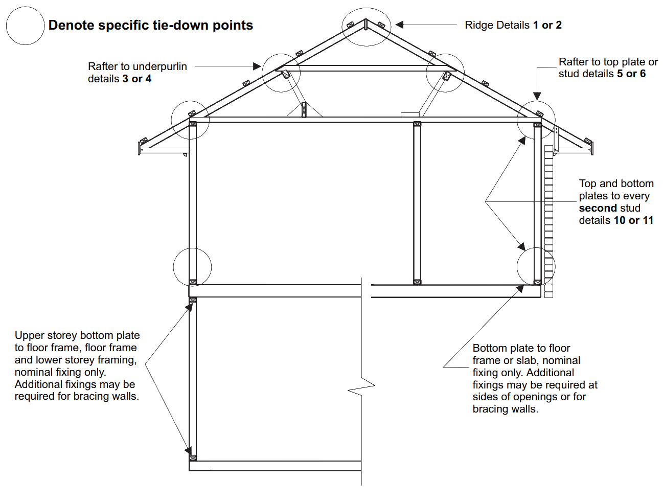
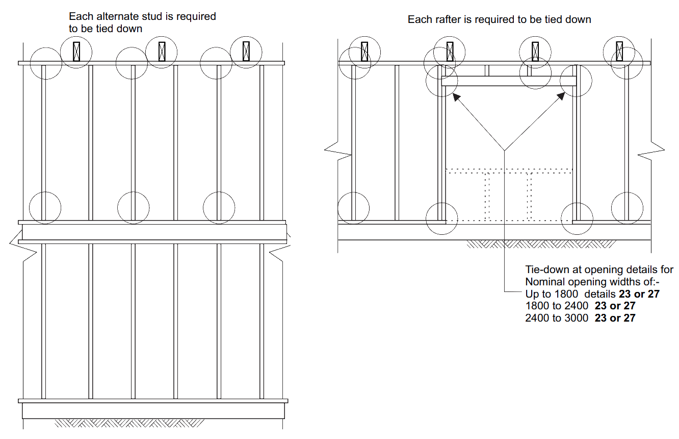
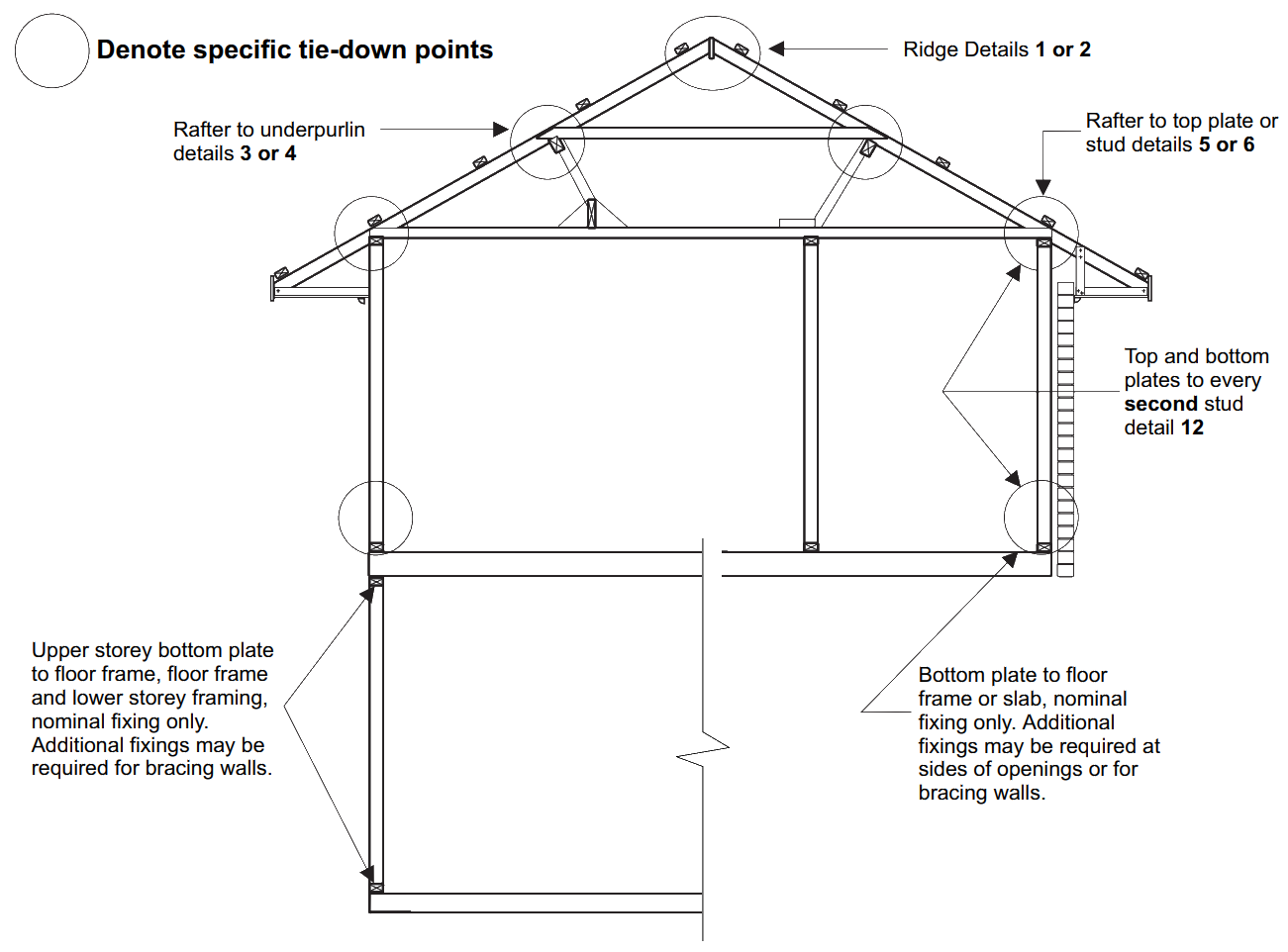
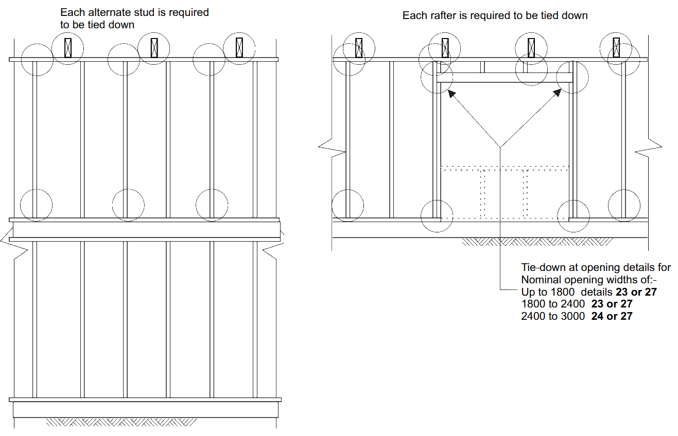
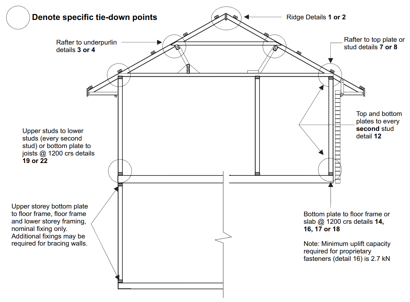
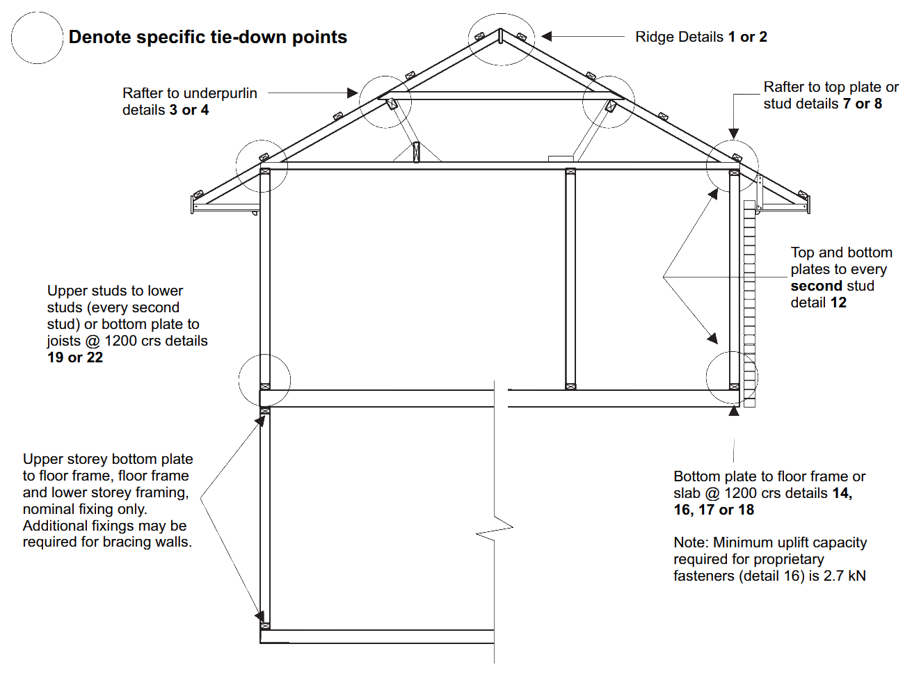
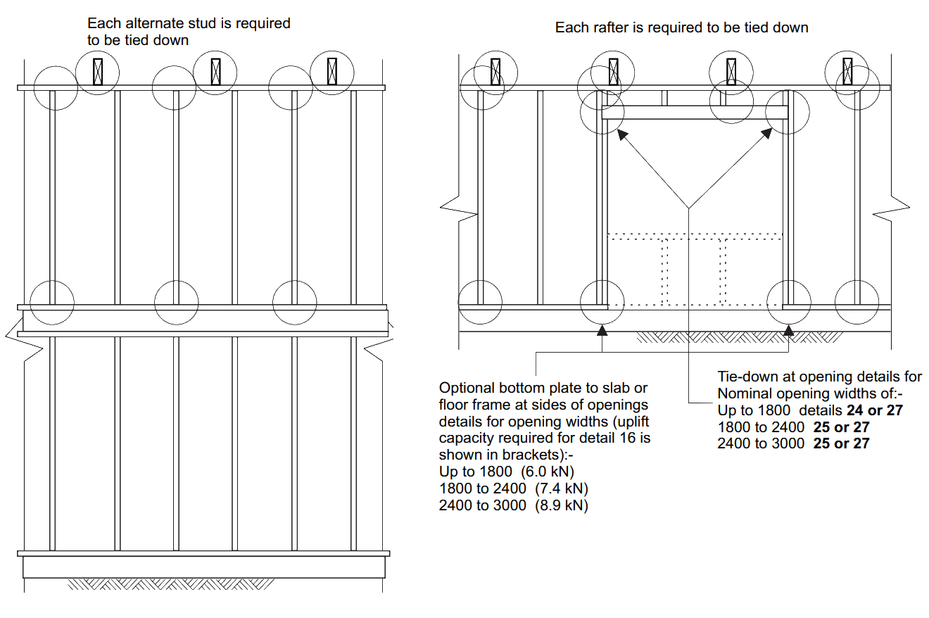
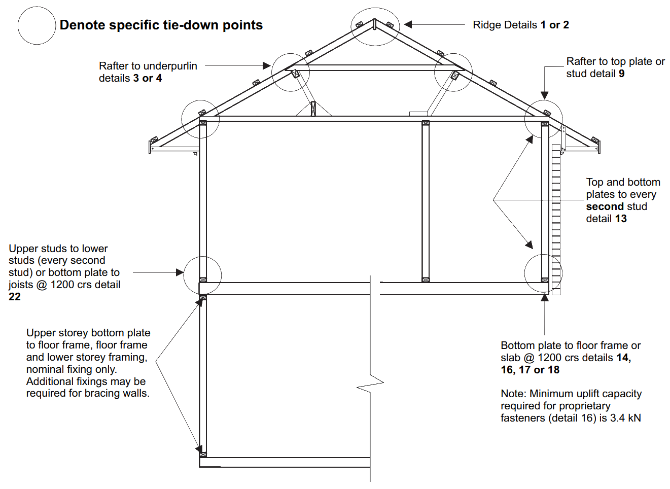
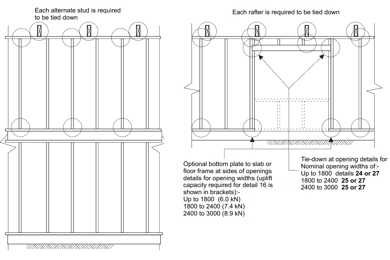
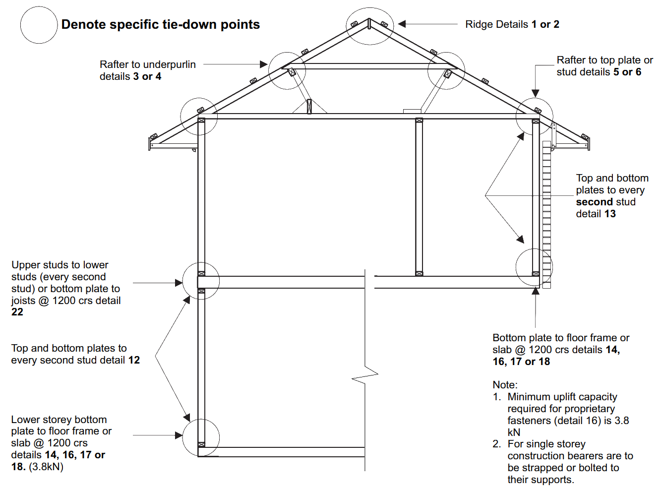
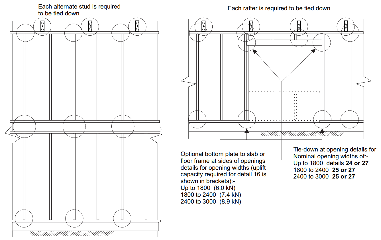
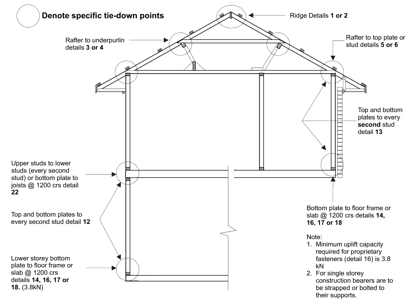
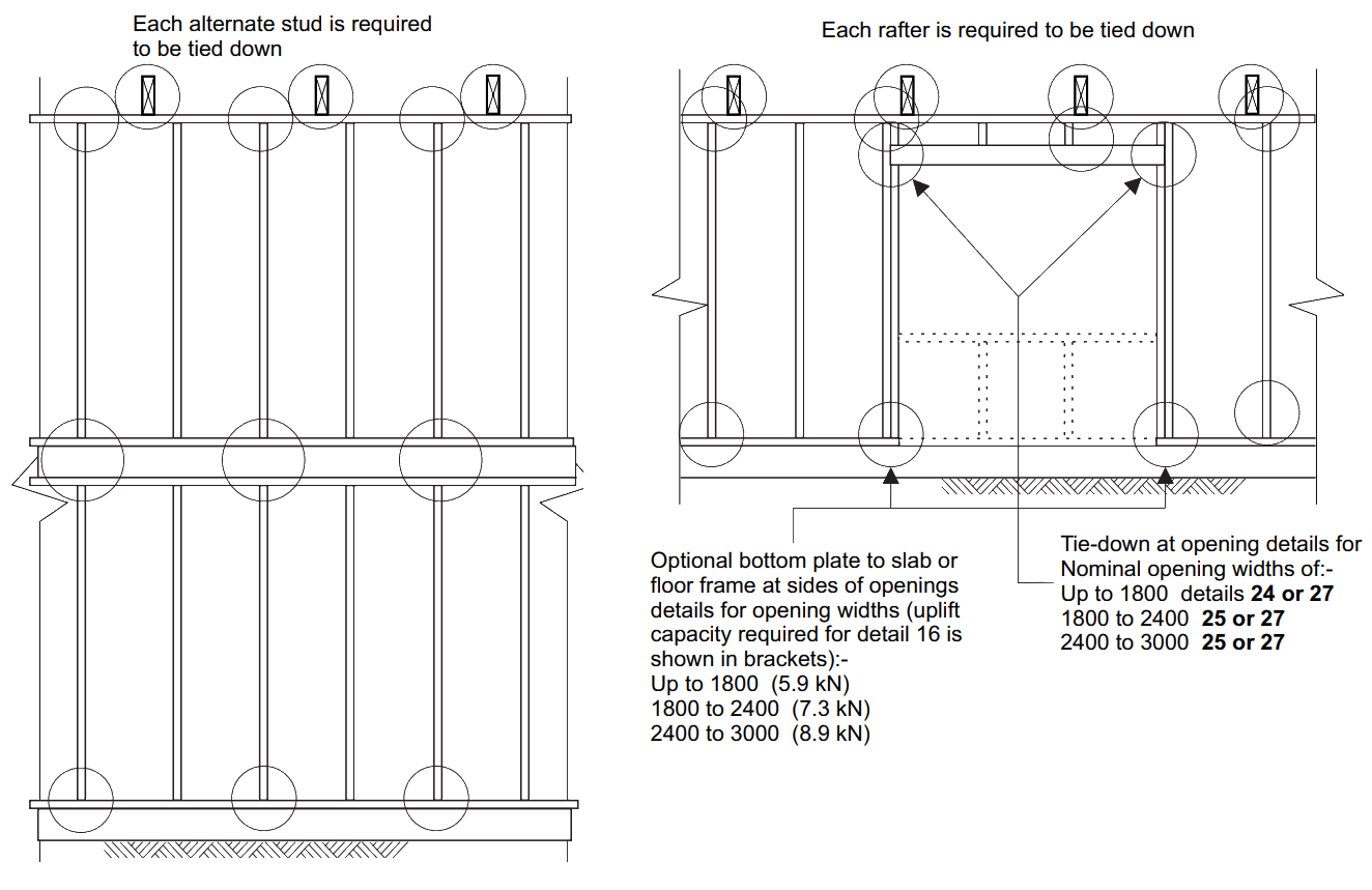
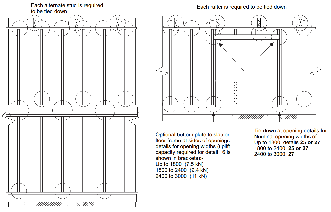
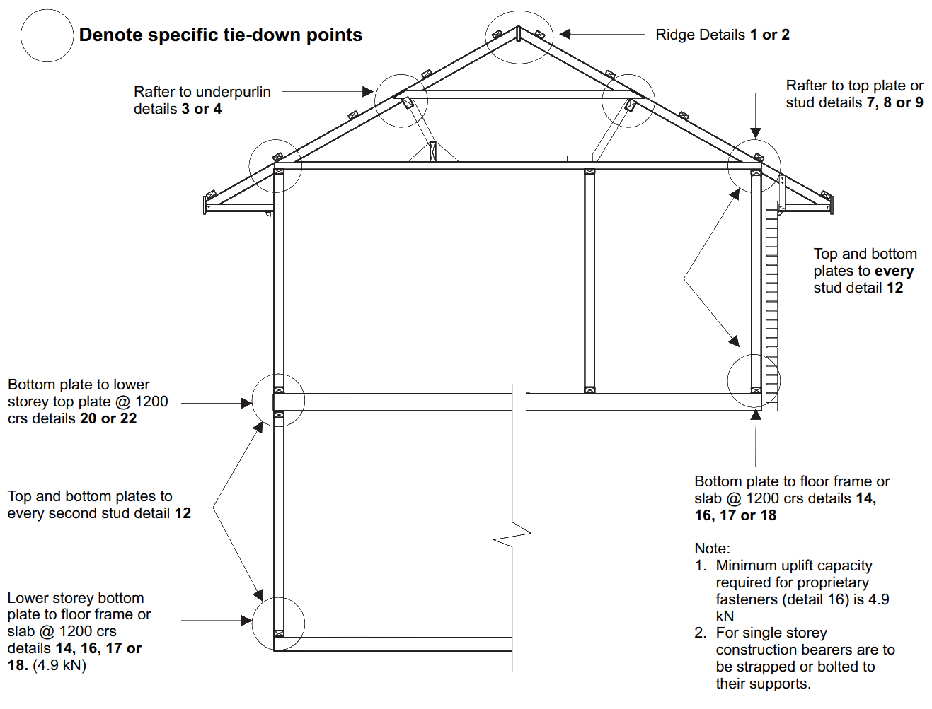
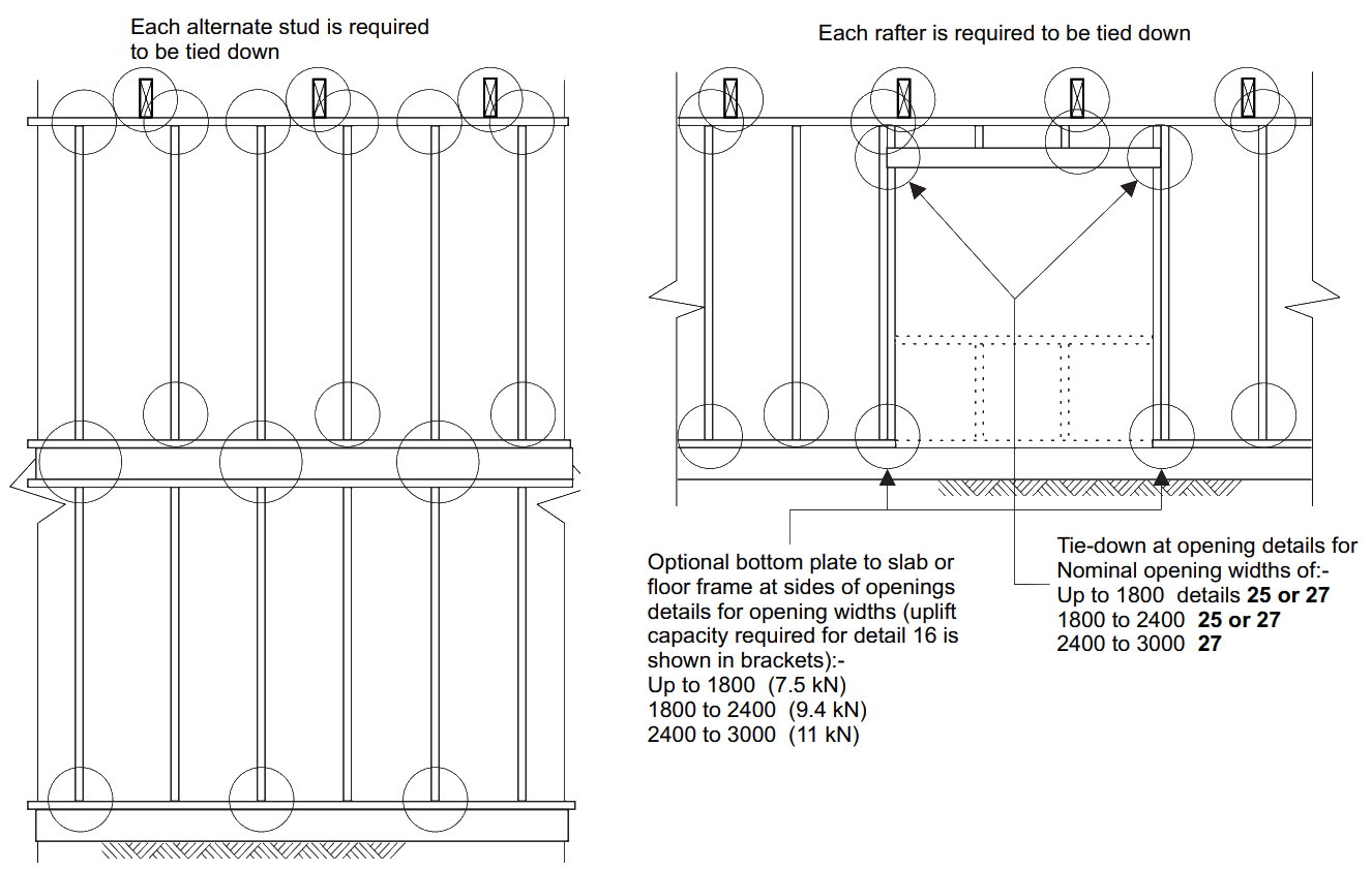
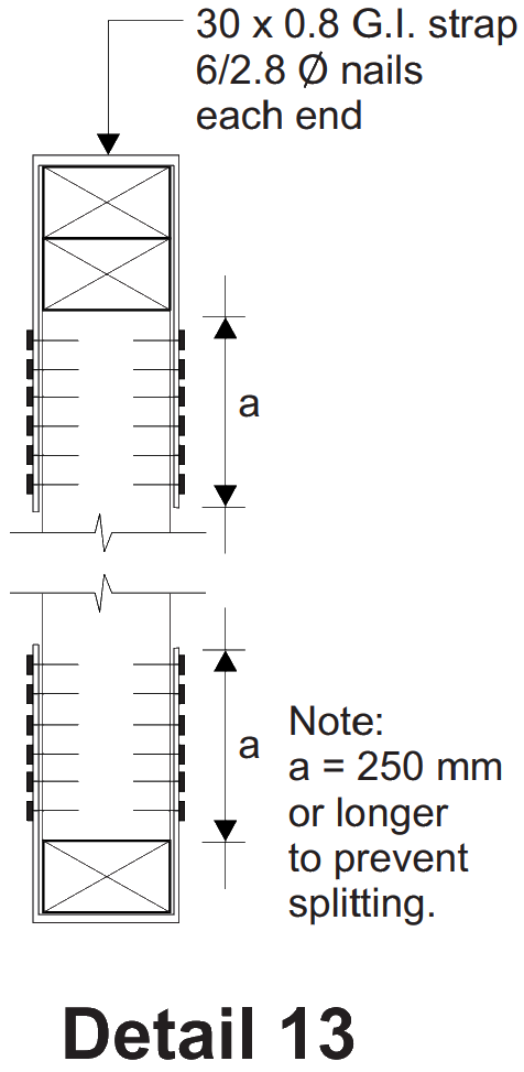
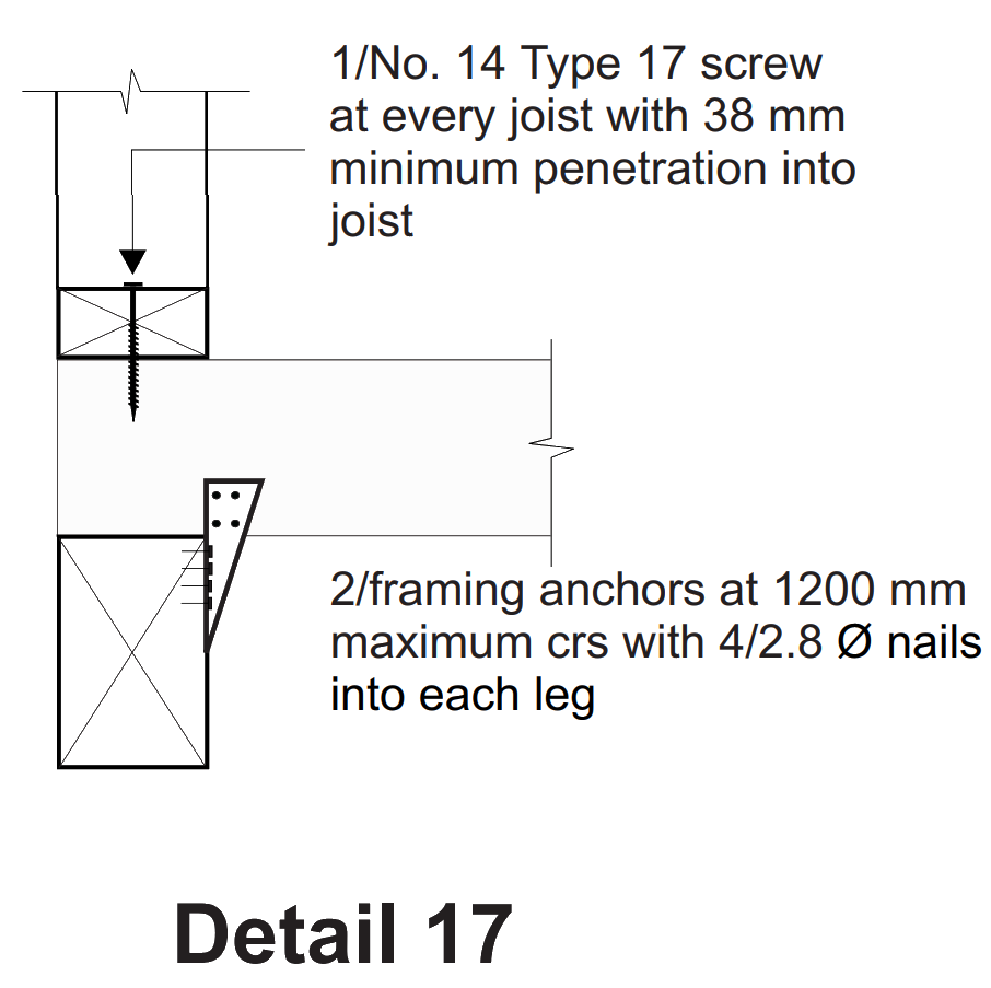
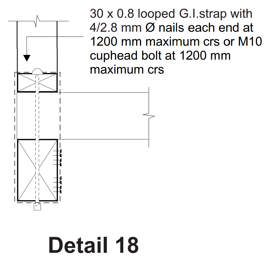
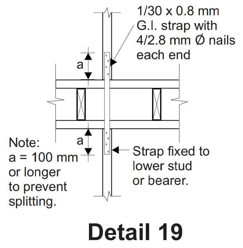
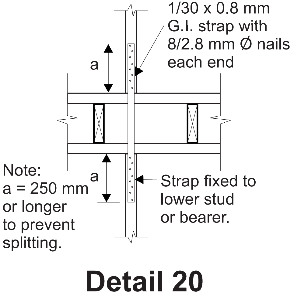
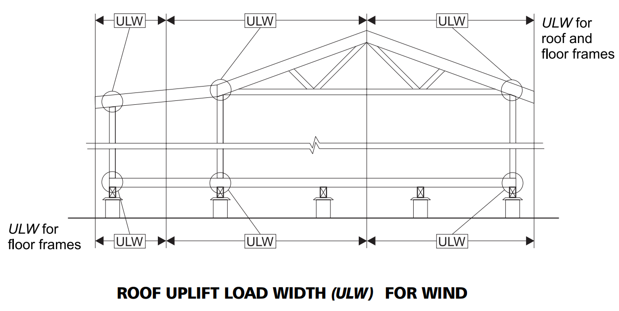
AS 1684.2, Clause 9.6.1 states that “continuity of tie-down shall be provided from the roof sheeting (sheeting in this sense also applies to roof tiles) to the foundations”. For ‘pitched’ coupled roofs, where there is net uplift that cannot be resisted by nominal nailing alone, the code requires specific tie-down fixings to be installed. From Tables 9.2 and 9.5, it can be seen that these specific tie-downs are required for N1, N2, N3 and N4 sheet roofs and N3 and N4 tile roofs. This guide only covers N1 & N2 sheet roofs and N3 tile roofs. Simplified details for a limited range of building spans and member and tie-down spacings are provided in this guide and accompanying sheets for the following conditions:
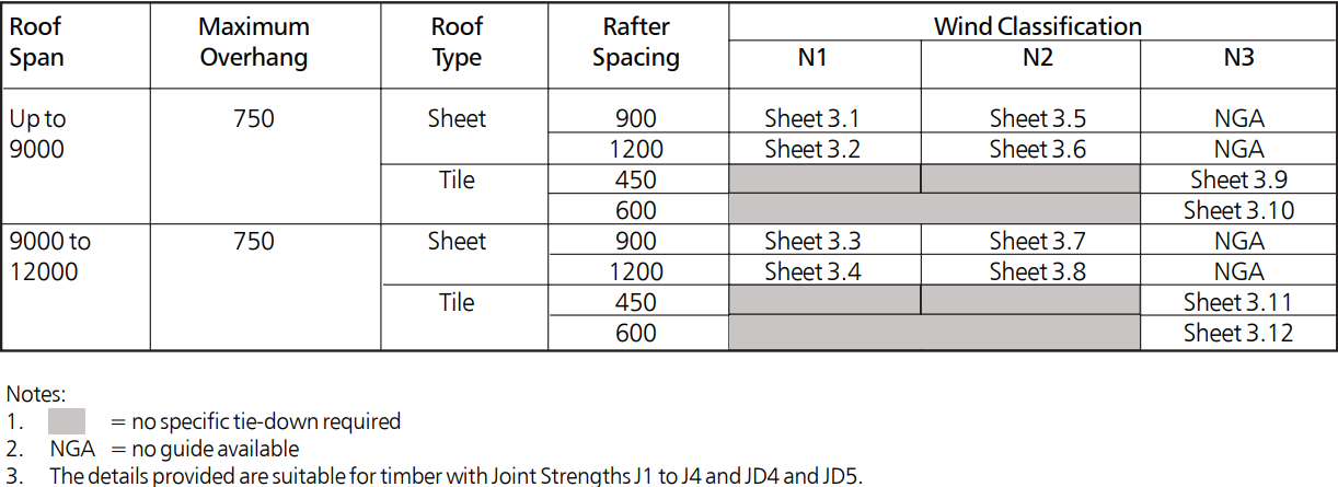
Table 1: Diagram key for simplified connections
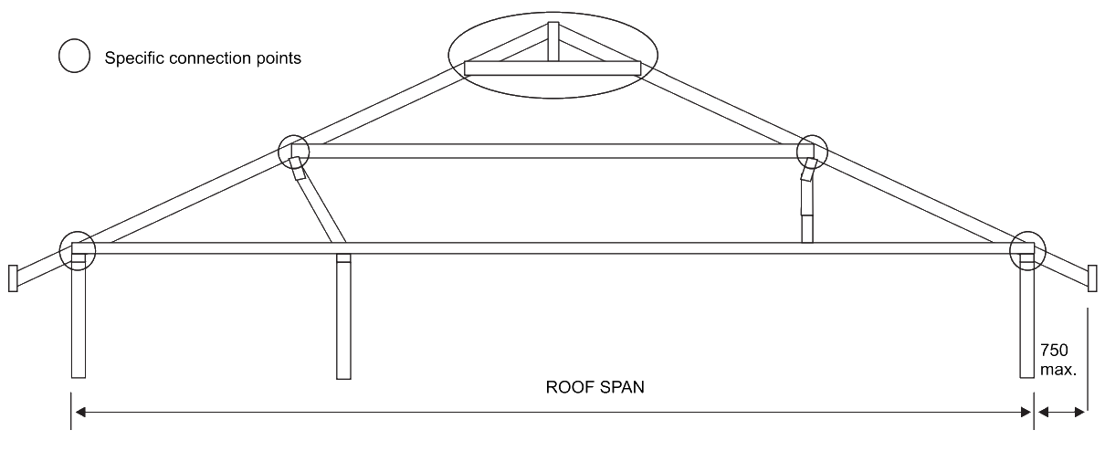
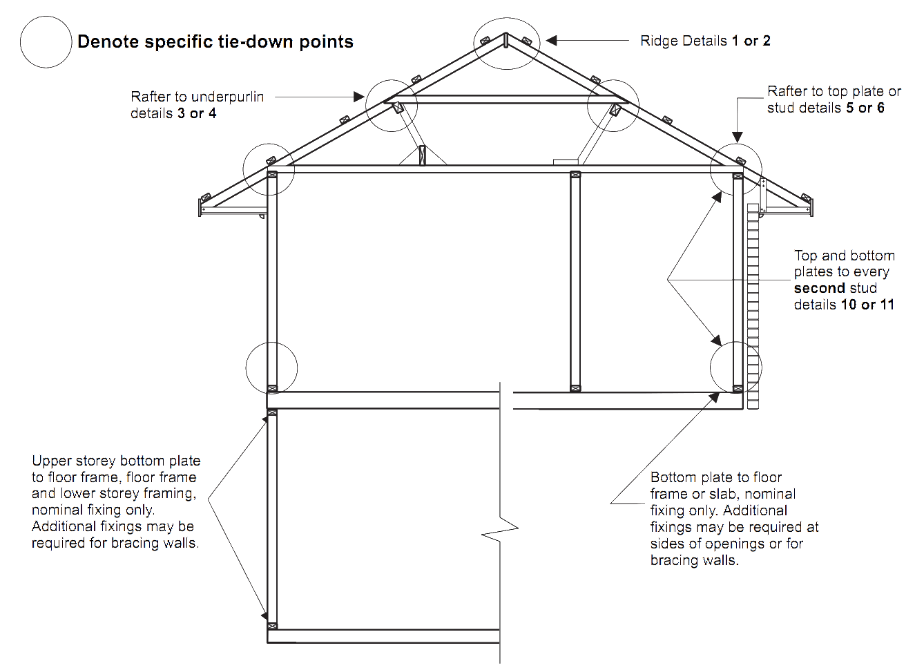
Figure 1: Specific connection points for a typical roof span


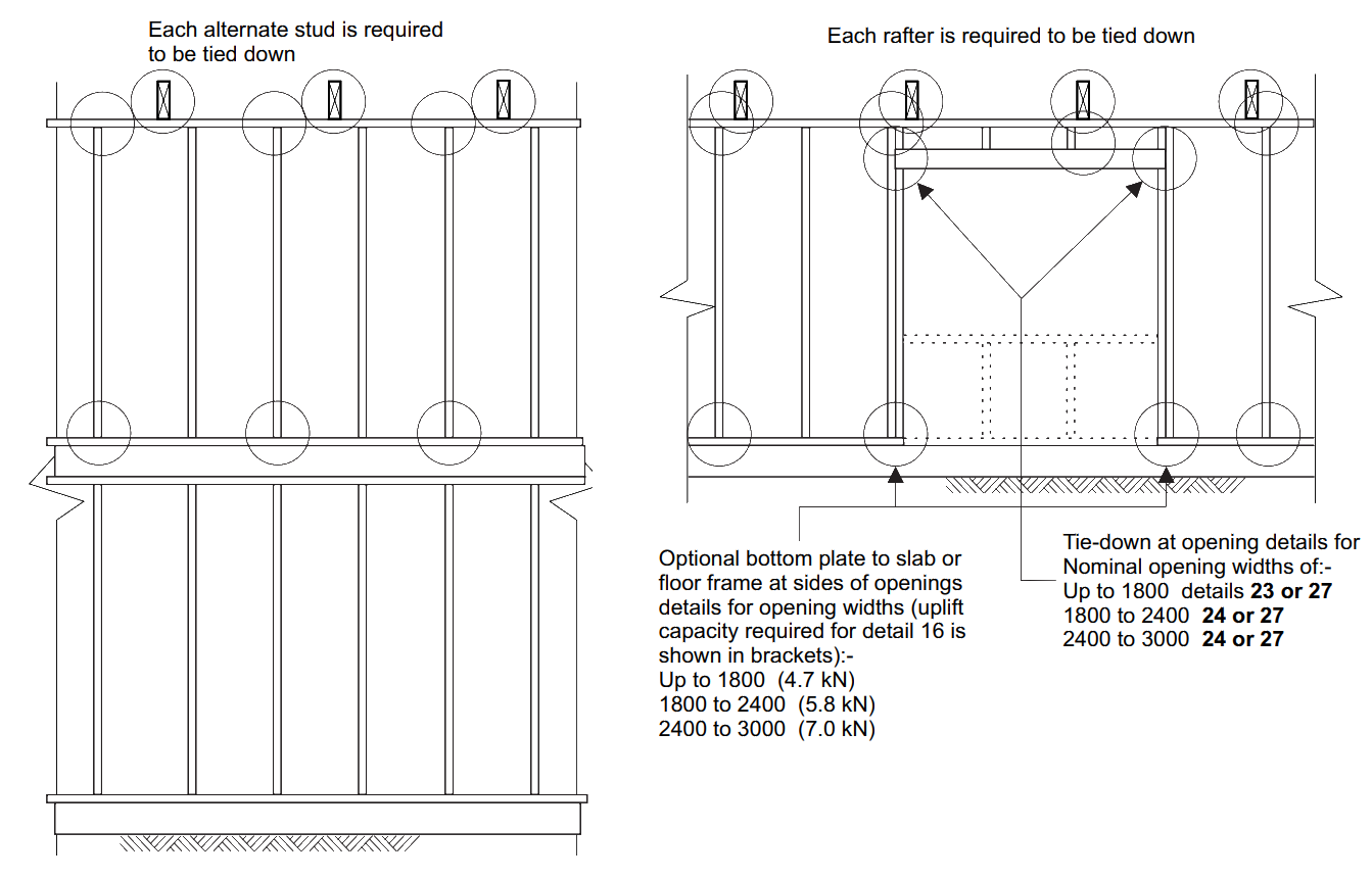
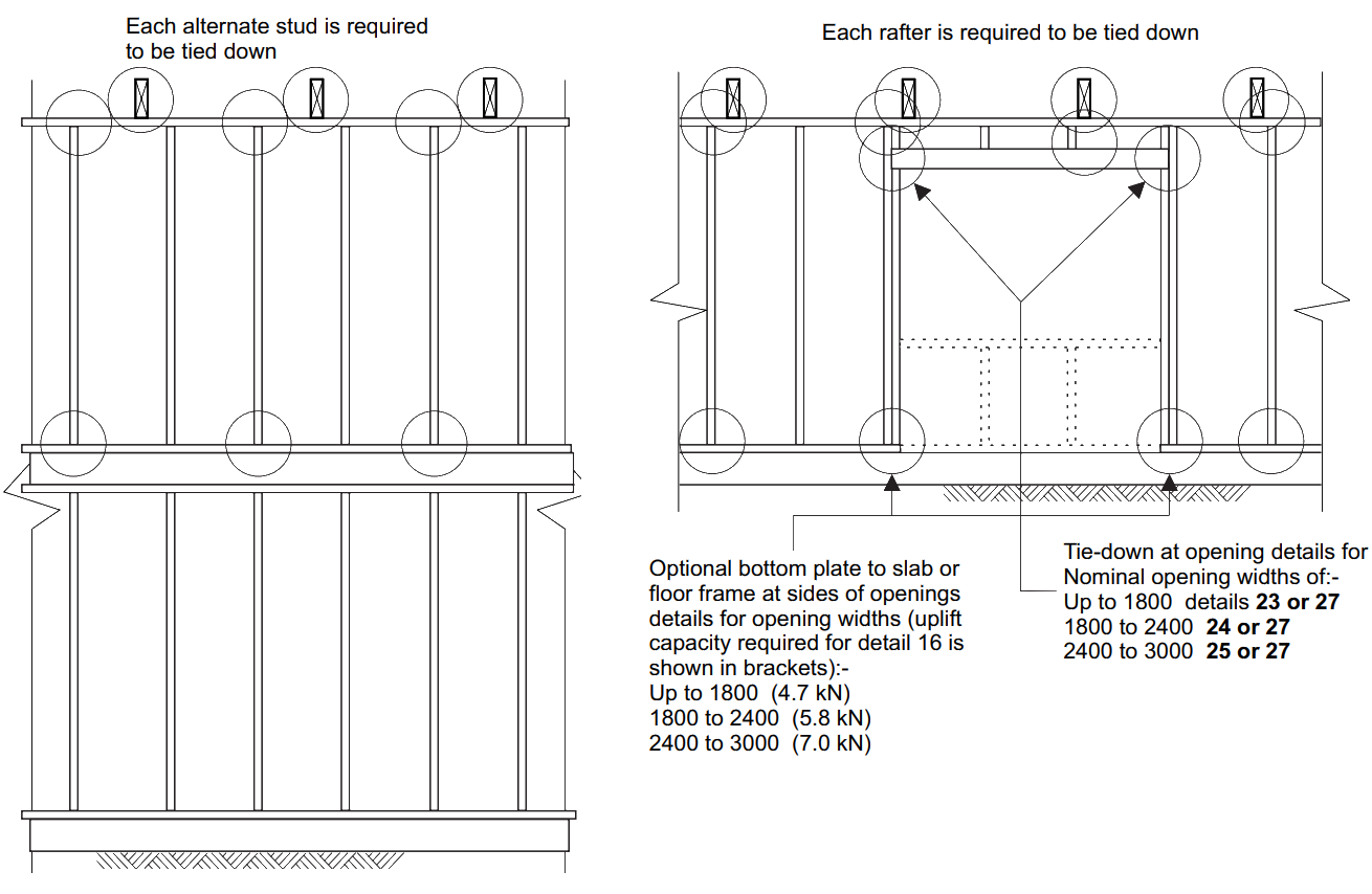
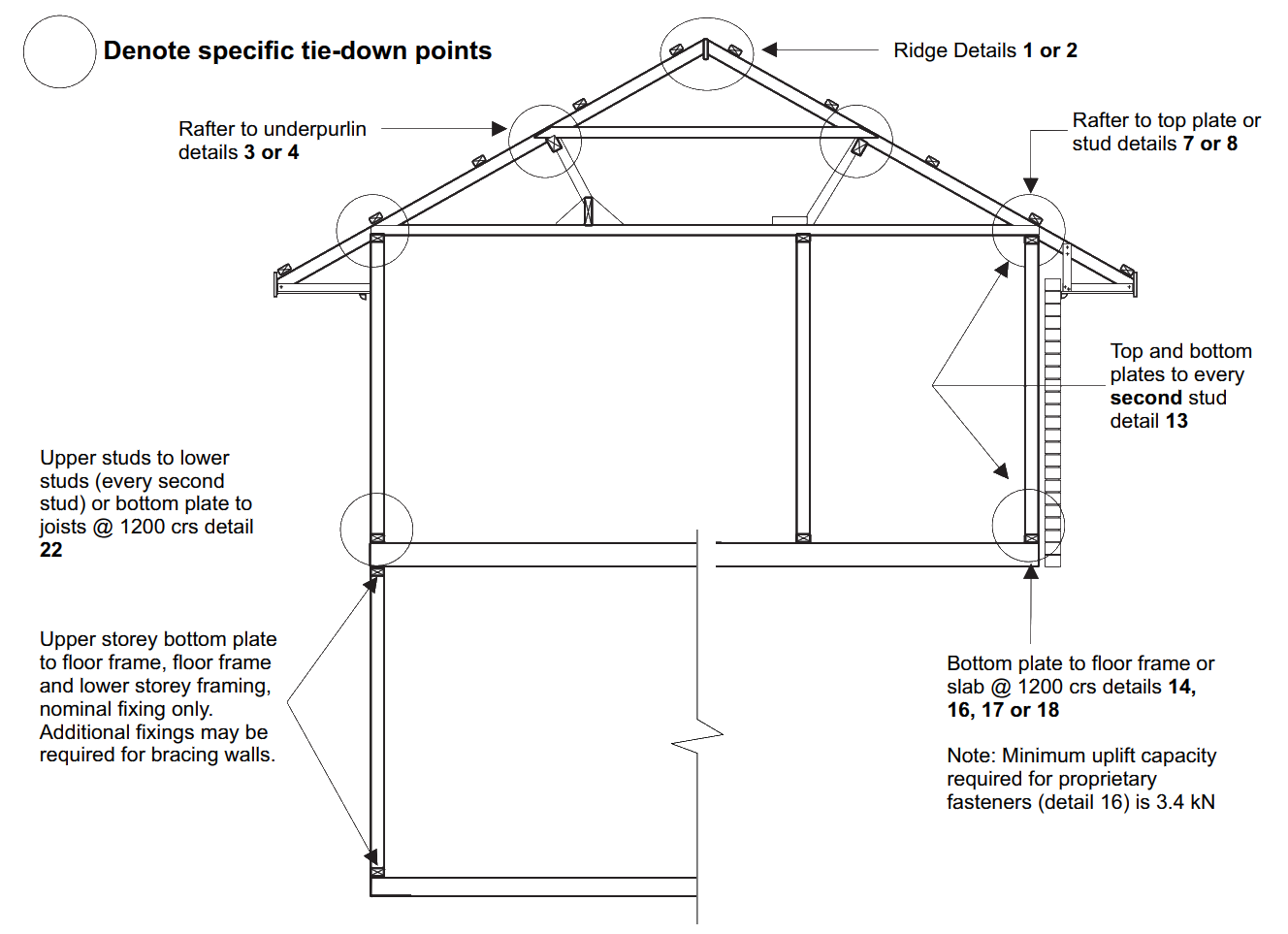
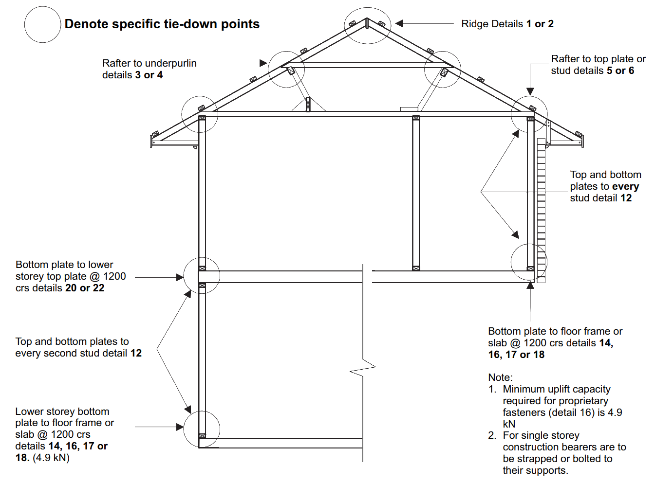
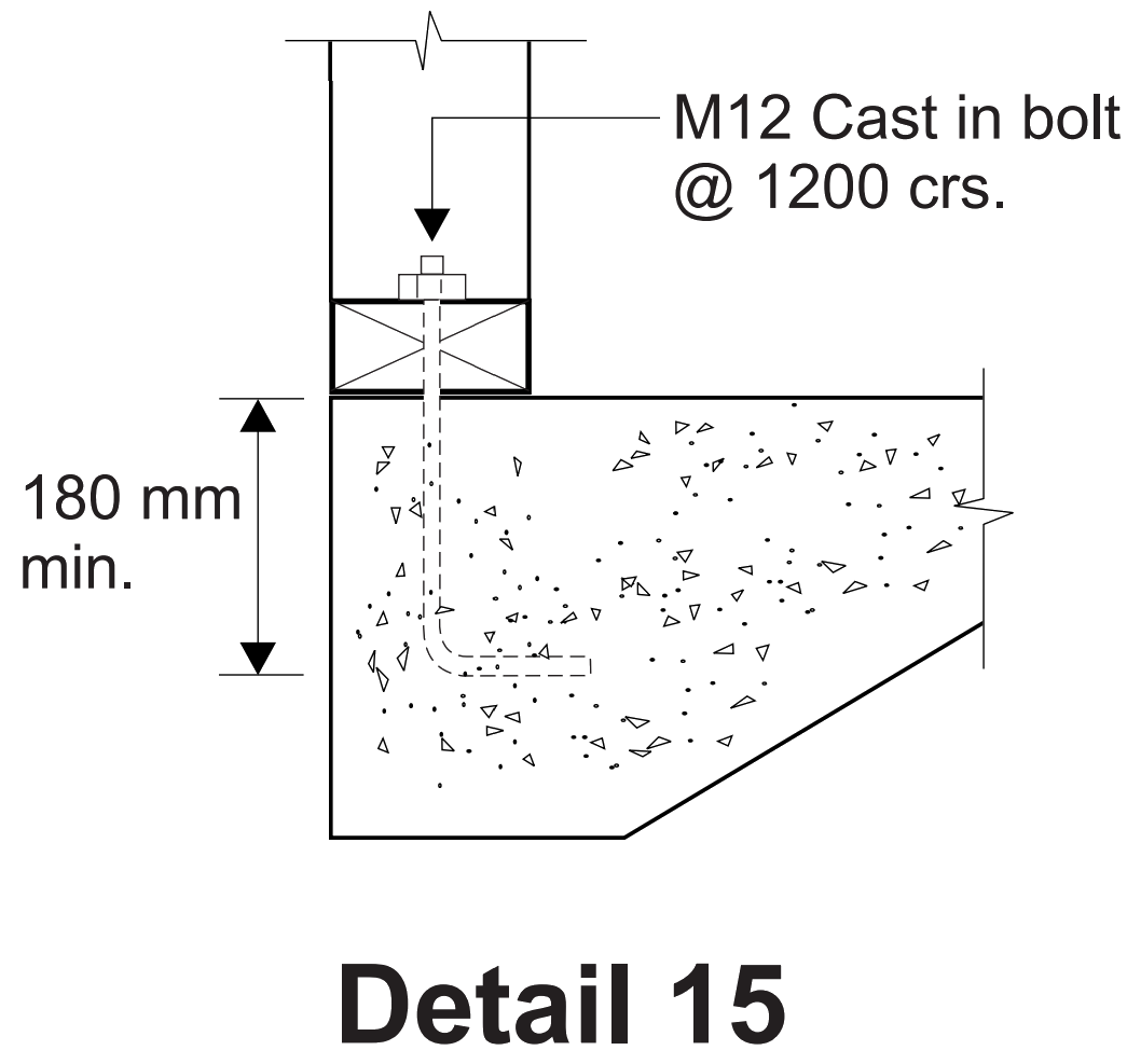
Detail 15
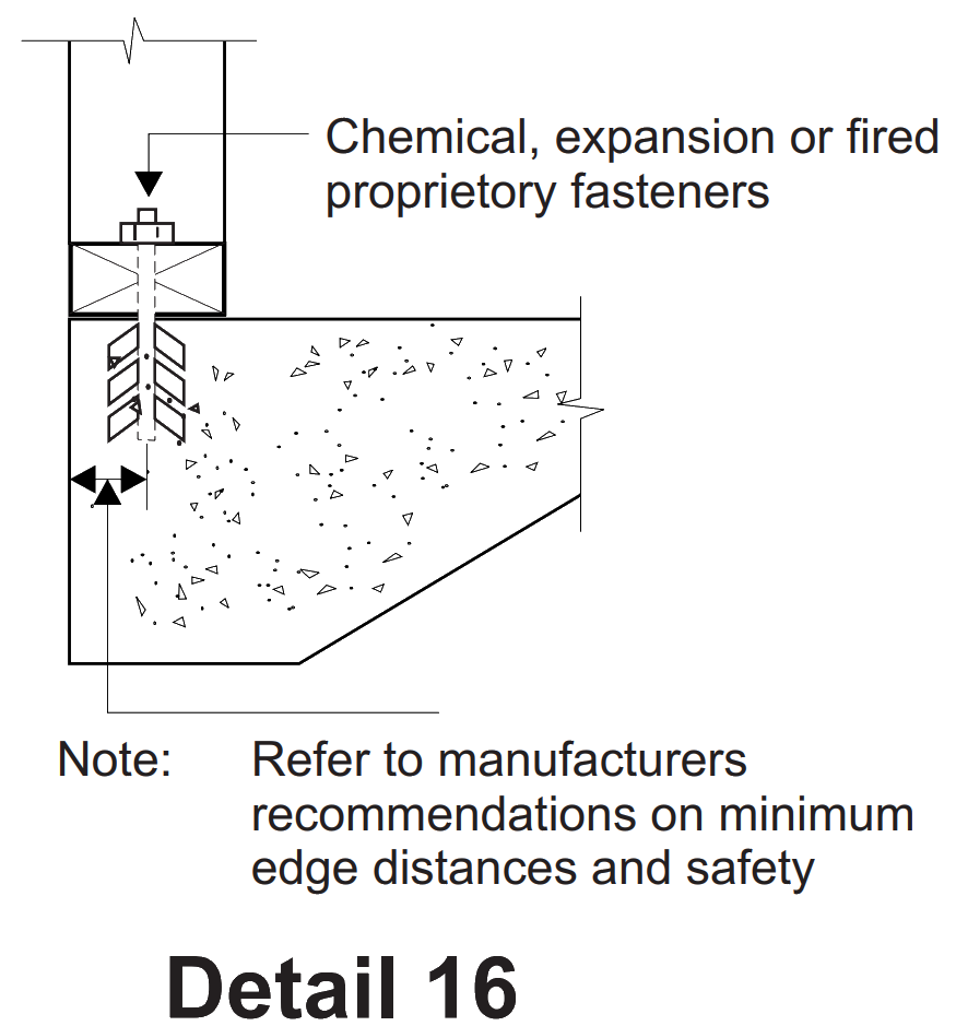
Detail 16

Based in WoodSolutions AS 1684 User Guide 4, 2012. All references have been updated to the 2021 version of AS 1684
Figure 1.2 in AS 1684 Parts 2 require a maximum external wall height (floor to ceiling) of 3000 mm. The span table supplements to the code, on the other hand, provide stud sizes for heights up to 4800 mm where permitted for the relevant size and grade of stud. The overriding 3000 mm height limitation was included in the Code to ensure that other design assumptions and requirements inherent in the Code would not be compromised. These included the basis for determination of the racking and overturning forces and the resistance of nominal connections and bracing materials including uplift at ends of bracing walls and the magnitude of shear forces. It was recognised that if the Code could be extended to cater for wall heights up to 3600 mm (the old 12 ft ceilings), that this would increase its value particularly with respect to renovations and extensions to older housing stock.
Prior to determining the "rules" that would permit the Code to be applied to 3600 mm high walls, a sensitivity check was carried out to determine the effect these higher walls would have on the remainder of the code. The parameters that were investigated included the following:
The size of studs, plates and lintels in external load-bearing walls can be determined directly from the relevant span tables in the supplements to AS 1684 Part 2 and Part 3.
The span tables in the supplements to AS 1684 Part 2 and Part 3 only extend to a maximum wall height of 3000 mm. Stud sizes for wall heights greater than 3000 mm will therefore need to be specifically engineered. This can be easily achieved using published computer software such as "Timber Solutions".
The total racking force shall be determined from Clause 8.3.4 but for external wall heights above 3000 mm up to 3600 mm, the lateral pressures determined from Table 8.2 to 8.5 for roof pitches 5 to 20 shall be increased by 10%.
Note: Pressures for other roof pitches or for vertical surface elevations (Table 8.1) do not require to be increased.
Determine the capacity of bracing walls greater than 2700 mm high from Table 8.19. For 4800 mm high walls, the bracing wall capacity/height multiplier is 0.56.
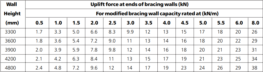
Include the following additional lines in Table 8.23 of Part 2 and Table 8.24 of Part 3:
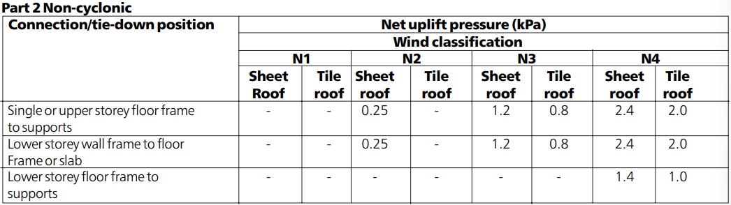
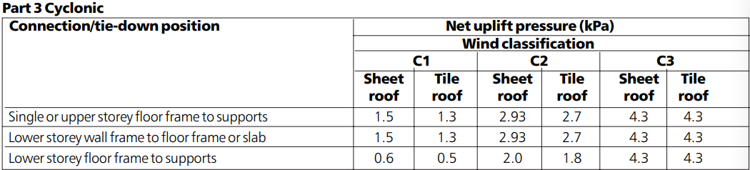
In Clause 9.6.4, the wind uplift forces calculated by multiplying the net uplift pressure by the area of the roof contributing to the tie-down, shall be determined from Table 9.5 using the following net uplift pressures for the tie-down positions described:
Note: The uplift forces given in Tables 9.6 to 9.10 shall not be used for determination of uplift forces however, they could be recalculated using the net uplift pressures given above.
Add the following NOTES to Table 9.29 to cater for 300 mm and 3600 mm high walls:
NOTES:
Appendix G shall not be used to determine racking forces for wall heights from 3000 mm to 3600 mm.
Based in WoodSolutions AS 1684 User Guide 5, 2012. All references have been updated to the 2021 version of AS 1684
The tops of internal bracing walls are required to be fixed to the floor, ceiling or roof diaphragm (or more correctly, the floor/ceiling/roof diaphragm is required to be fixed to the tops of bracing walls) to enable lateral loads (racking forces) which occur on the external walls and roof, to be evenly distributed into all the bracing walls, including the internal bracing walls.
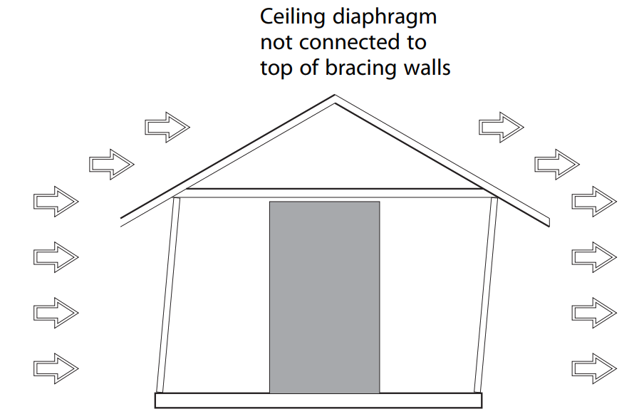
Figure 1: Ceiling diaphragm not connected to top of bracing walls
Internal bracing walls can be connected to the floor/ceiling/roof diaphragm either directly (a connection at the actual position of the bracing wall) or at some other position in the same wall but away from the actual brace. For this latter case, the top plate in the wall will need to provide a continuous tie from the braced section of wall to where the top plate is connected such as at an external wall.
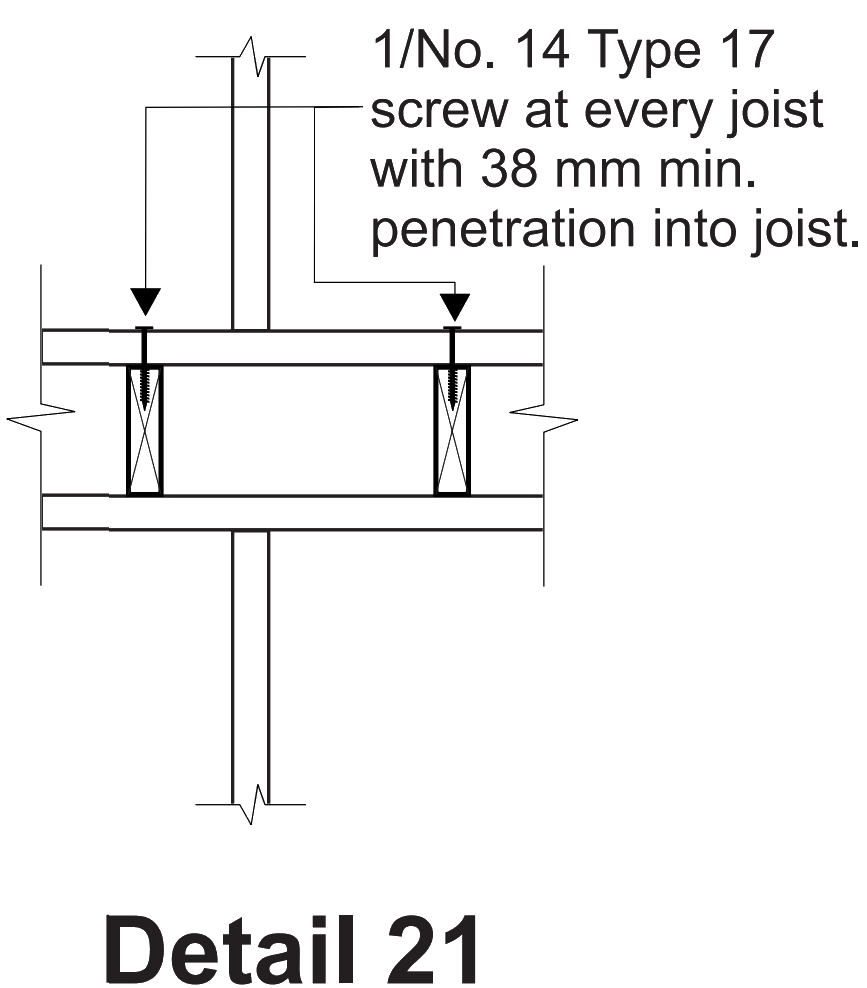
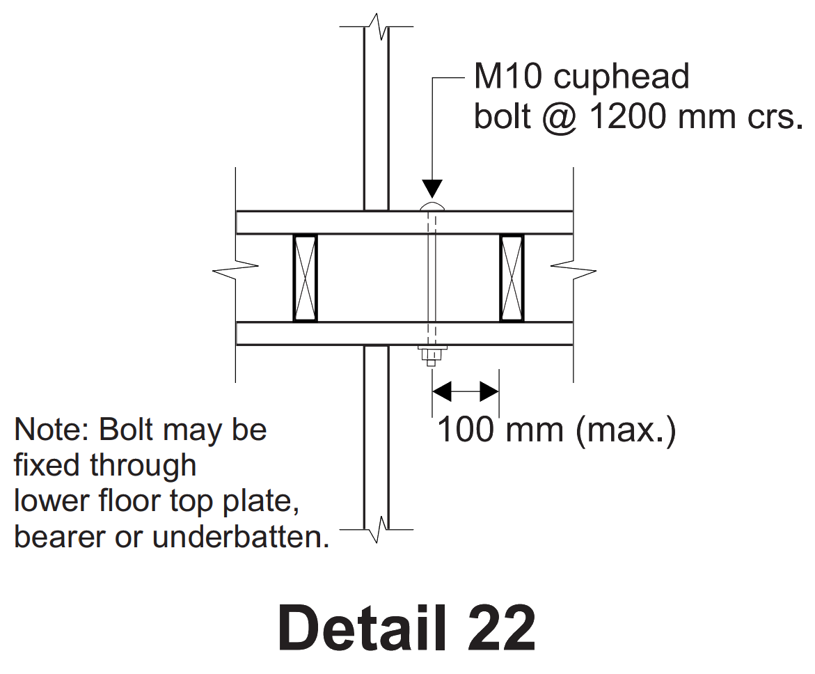
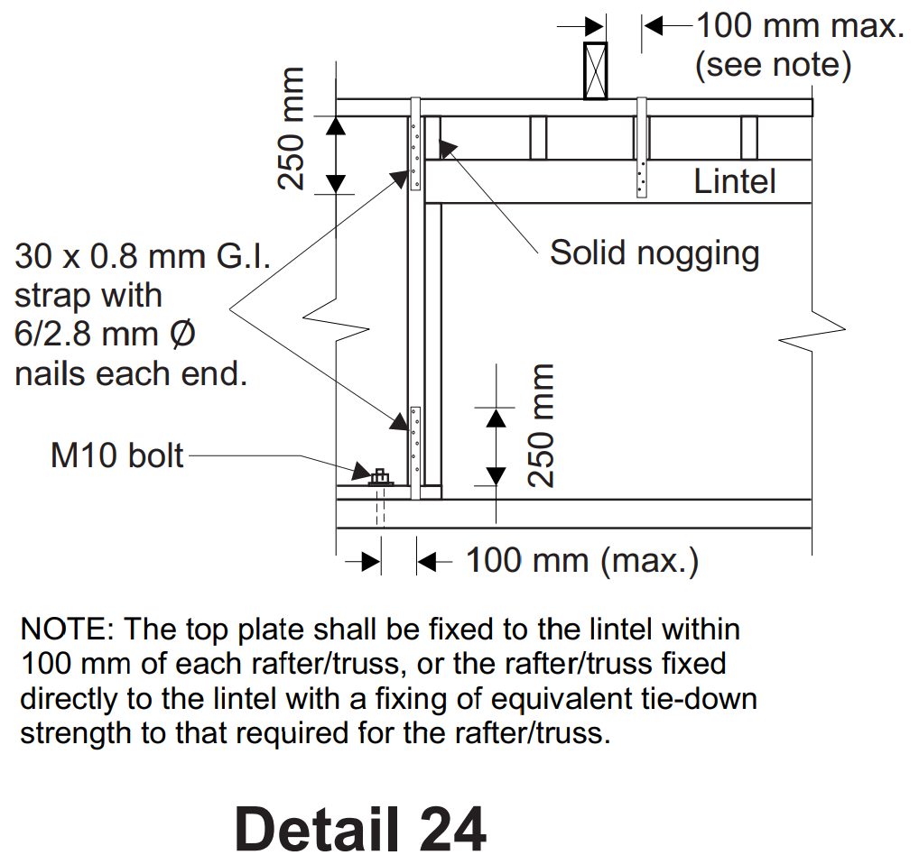
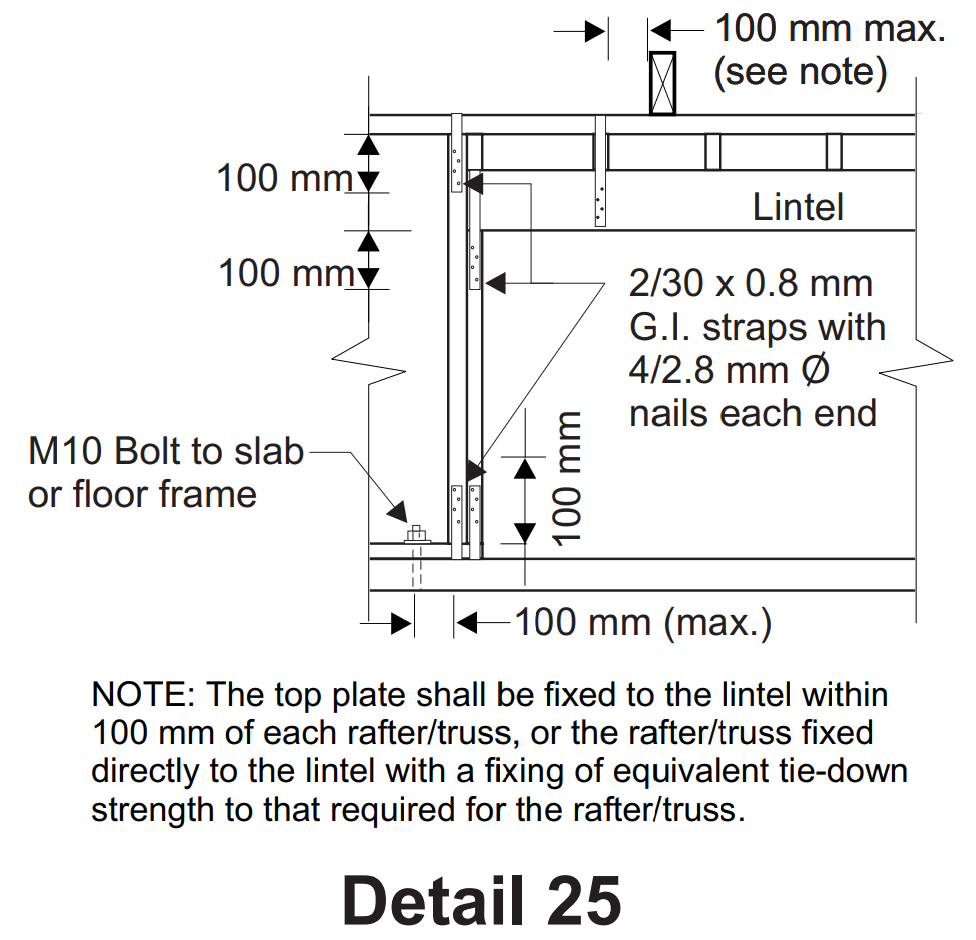
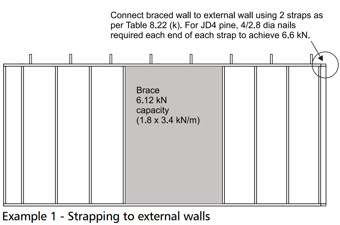
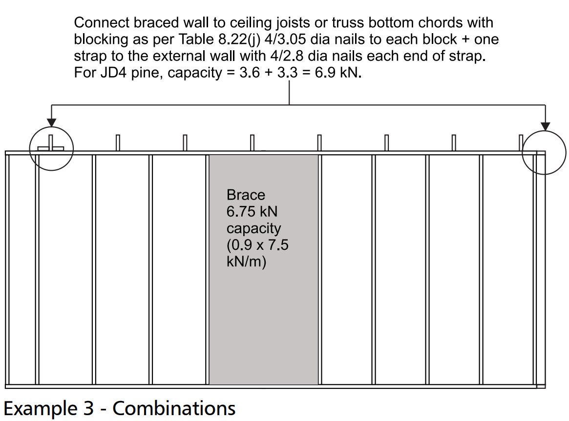
The following examples are provided to illustrate acceptable methods for connections at the top of bracing walls, that satisfy the requirements of o Clause 8.3.6.9 of AS 1684 Part 2 and Part 3.

Based in WoodSolutions AS 1684 User Guide 6, 2012. All references have been updated to the 2021 version of AS 1684
Some Code users are reported to be applying AS 4440 'Installation of nail plated timber trusses', as a basis for determining roof truss tie-down and avoiding the minimum nominal connection requirements specified for roof trusses in Table 9.4 of AS 1684 Part 2 and Part 3.
AS 4440 Clause 3.7 states that "the requirements for fixing trusses to the supporting structures shall be in accordance with the approved specifications."
This clause clearly indicates that prescriptive tie-down requirements for roof trusses are beyond the scope of AS 4440 and that details for tie-down have to be determined from other sources.
AS 1684 Part 2 and Part 3 on the other hand, provides procedures and prescriptive tie-down details including the minimum nominal fixings for roof trusses where there is no net uplift.
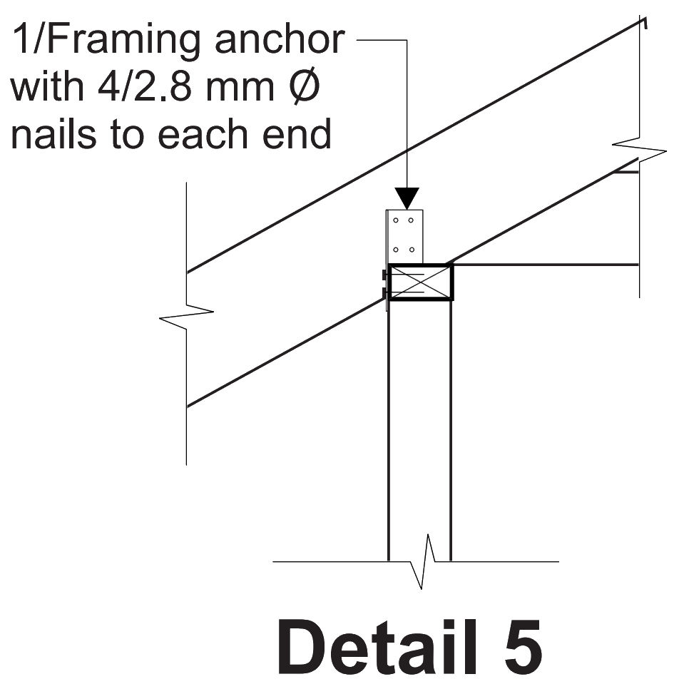
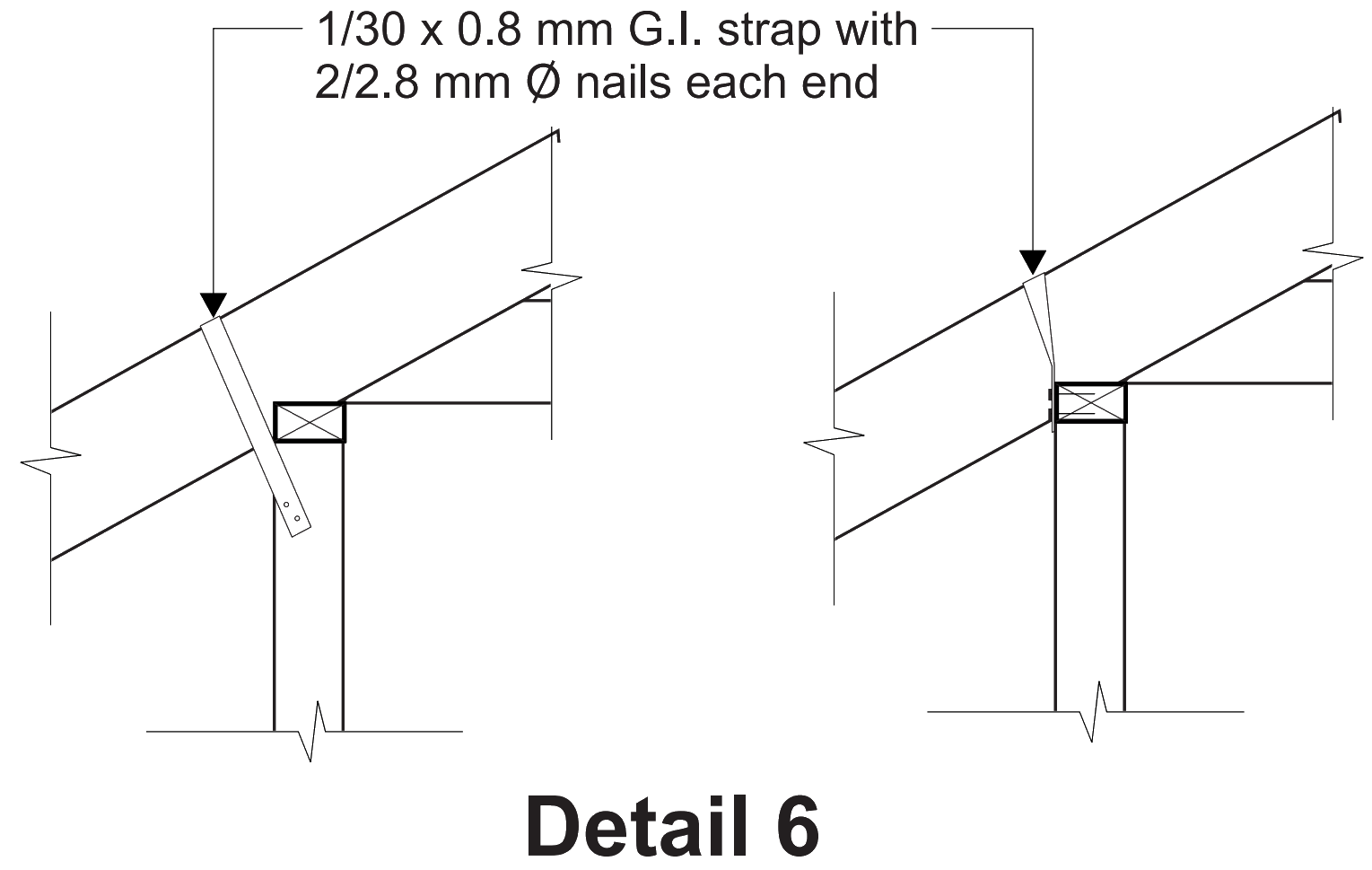
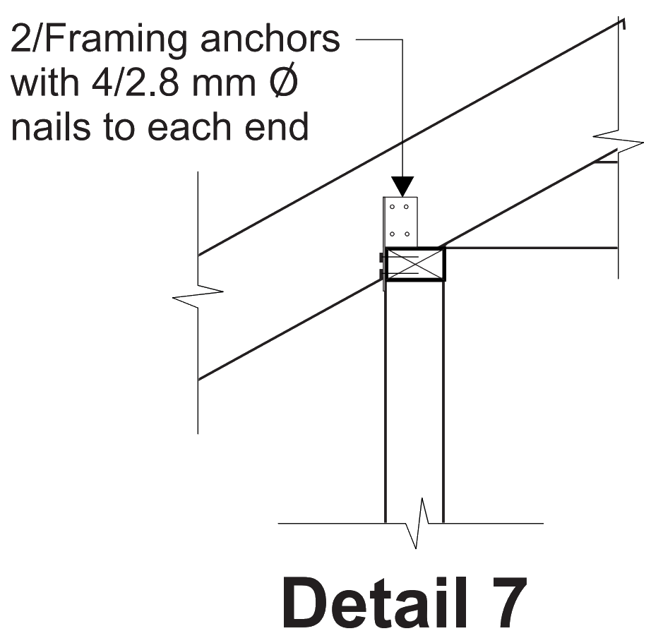
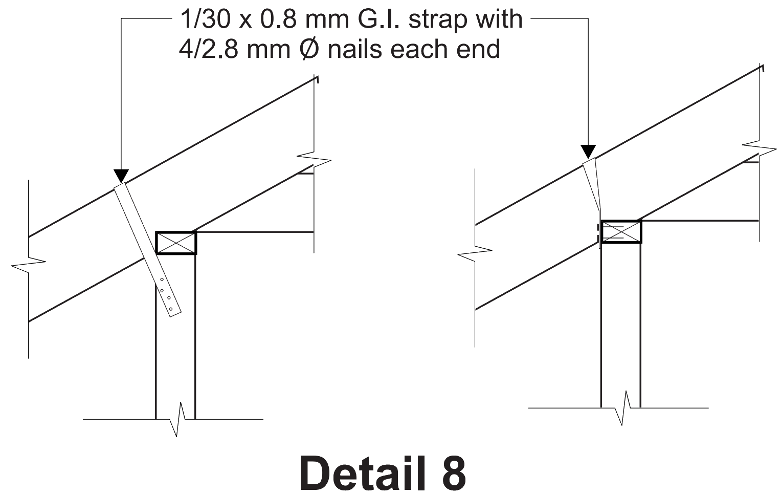
The minimum nominal connections given in Table 9.4 of one framing anchor or a strap plus skew nails are generally in accordance with the minimum connections recommended by the truss plate manufacturers. Unless alternative connection details are provided and certified by the truss plate manufacturer or a structural engineer, then the requirements of AS 1684 shall apply for the connection and tie-down of roof trusses.
Based in WoodSolutions AS 1684 User Guide 7, 2012. All references have been updated to the 2021 version of AS 1684
Tables 9.12 and 9.24 provide the net uplift forces and tiedown details respectively for ridge boards and hip rafters. For tile roofs in wind classifications N1 and N2, specific tie down of the ridge board and hip rafters is not required and nominal nailing is adequate. See also Guide Note 2, Tie-Down of Coupled Roofs.
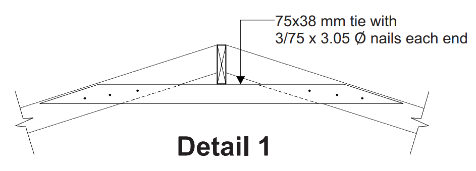
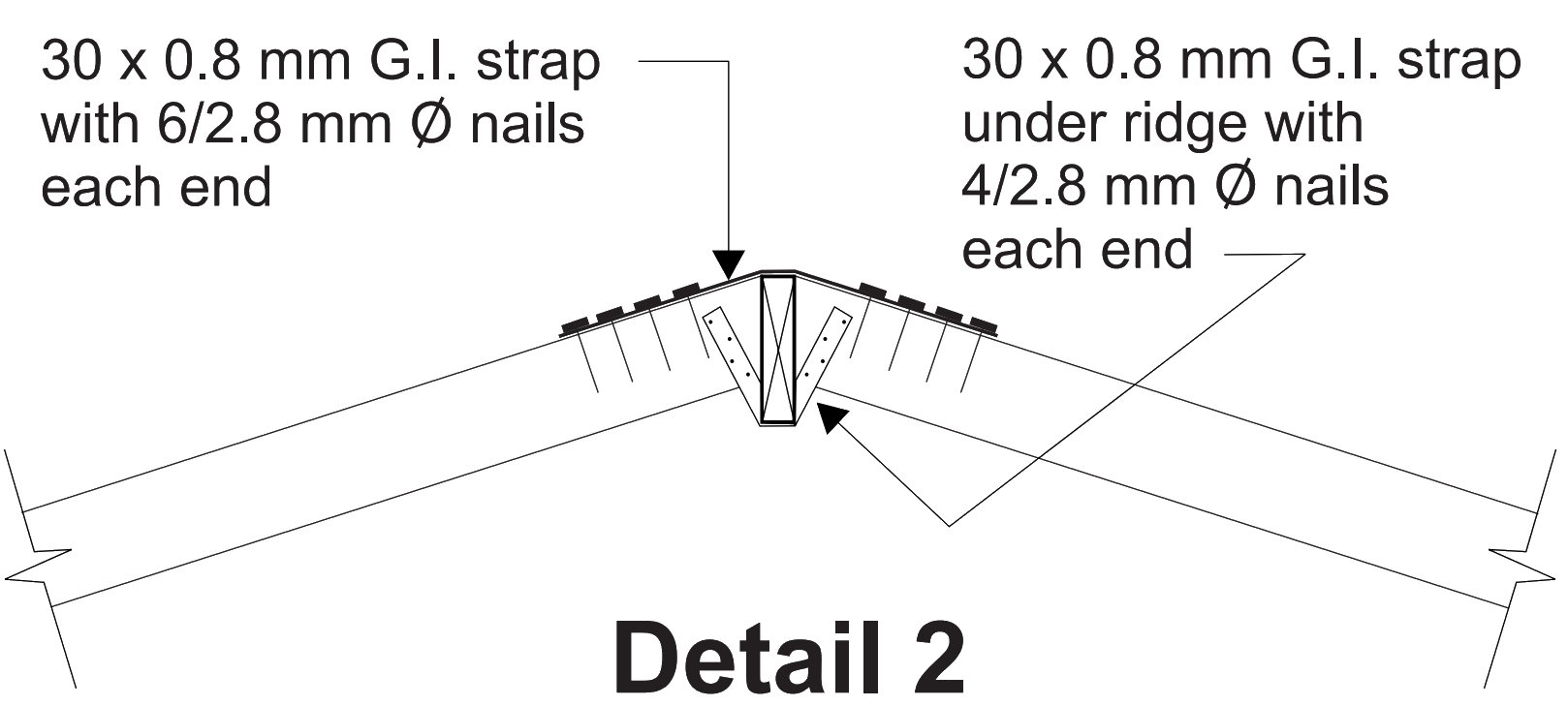
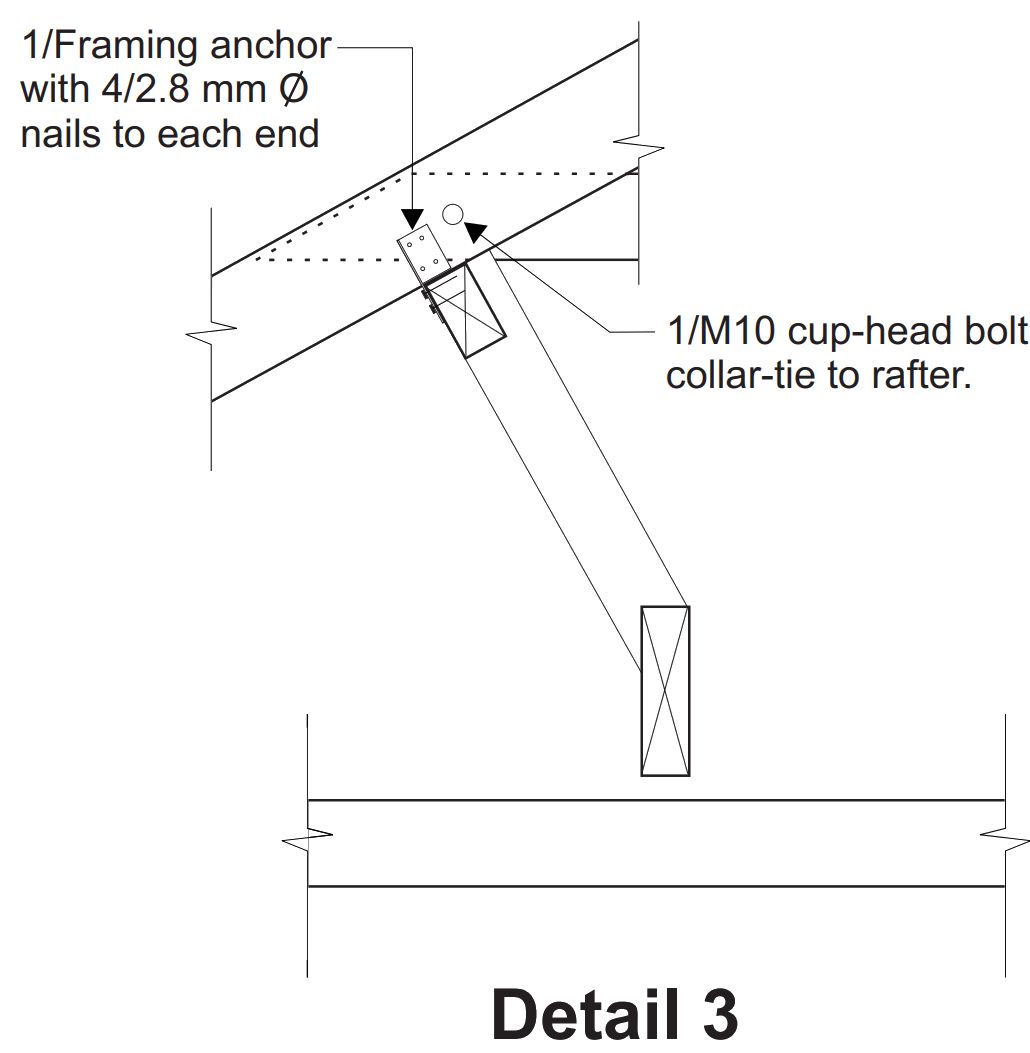
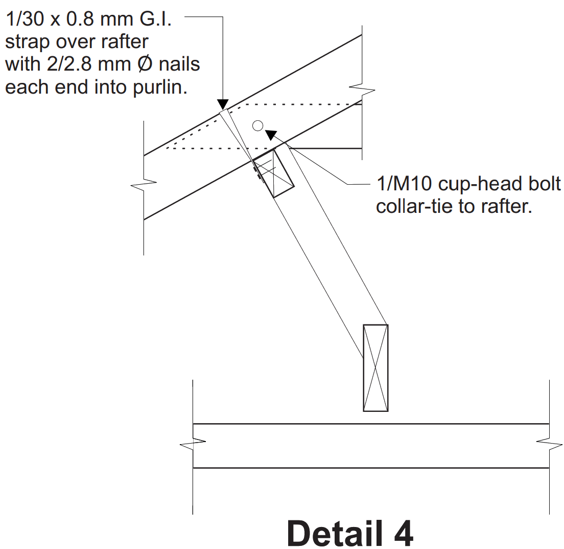
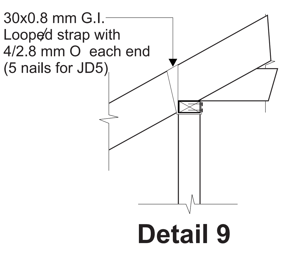
The diagrams in Table 9.24 indicate that the tie-down straps or bolts are vertical and the question is frequently asked, can they be at an angle and what happens if there is no wall directly under the tie-down points?
As is indicated in Table 9.23 for under purlins, tie-down at an angle to the vertical is acceptable for the same types of tie-down details.
It is recommended that the maximum angle that the tiedown straps or bolts are placed at does not exceed 30 from the vertical.
If there are no walls directly under the tie-down point or within the 30 angle, then the tie down can be taken to a strutting or hanging beam or similar and the ends of the beam can in turn be tied down to the wall frame or supporting structure using any of the appropriate connection details given in Table 9.16 to 9.22.
Note: If the ridge board or hip rafters are tied down to a beam, the uplift forces at the ends of the beam should be determined to ensure that it is proportional to the number and location of the tiedown from the ridge/hip.
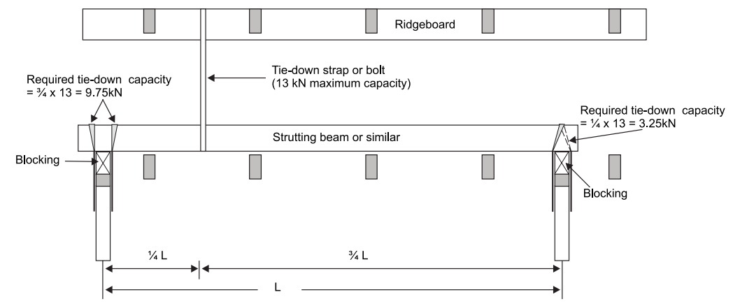
Figure 1: Ridgeboard tie-down rafter
Based in WoodSolutions AS 1684 User Guide 8, 2012. All references have been updated to the 2021 version of AS 1684
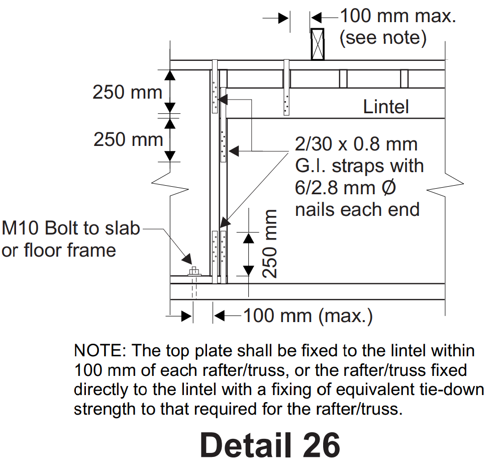
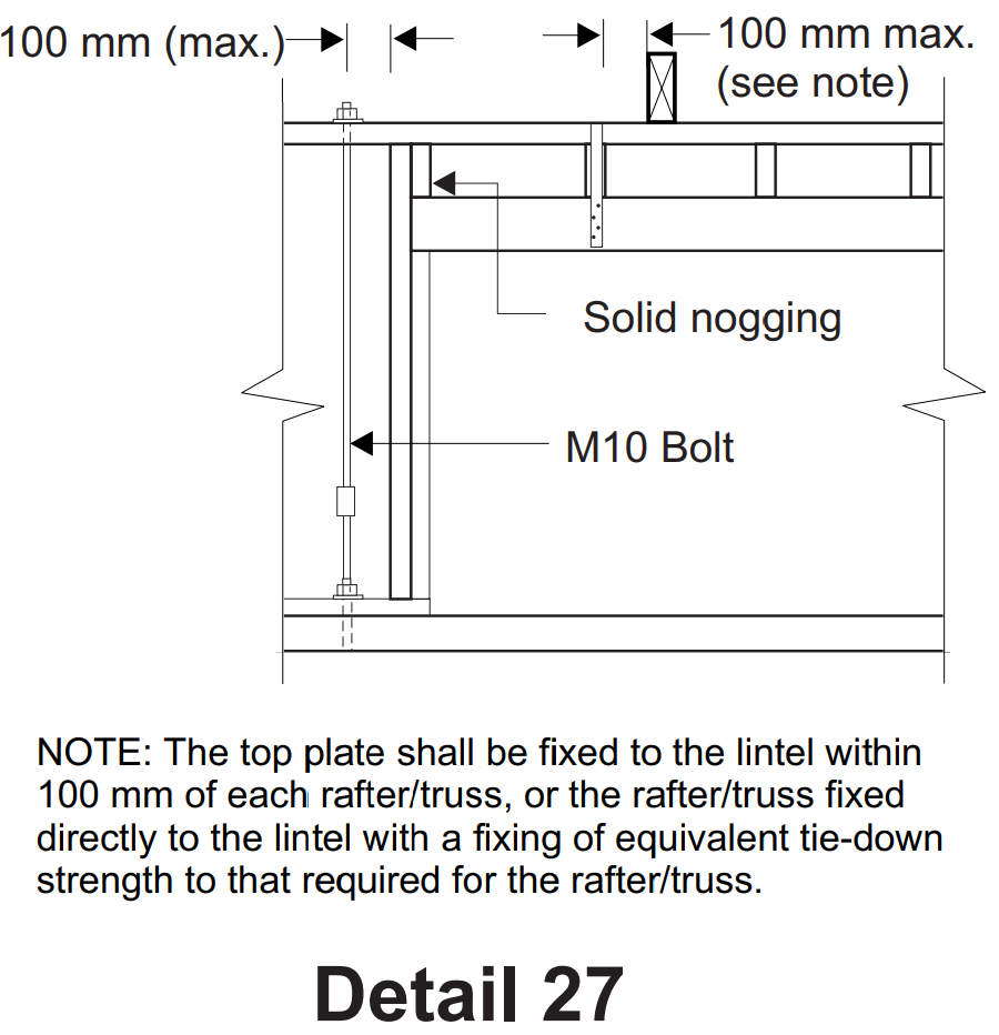
AS 1684 permits the use of proprietary masonry anchors for fixing bottom plates to concrete slabs. These fixings may be required for the purposes of resisting the uplift forces at the ends of bracing walls and/or the tiedown of walls due to wind uplift.
Table 8.24 (g), (Table 8.25 (g) in Part 3) and Table 9.18 (e) provide details for proprietary masonry anchors, which in turn refers to the manufacturer to obtain the uplift capacity. The uplift capacity obtained from the manufacturer must be a limit state design capacity for it to be compatible with AS 1684.
Note: The normal procedure that a manufacturer should undertake to establish limit state design capacities for their fasteners would be as follows:
Manufacturer's published capacities for masonry anchors may only refer to the tensile strength of the connection or the 'pull-out' strength from the concrete. It may not consider the bearing strength under the head of the fastener in the timber bottom plate or the head pull-through strength of the fastener in the timber bottom plate which in turn are influenced by the timber joint group.
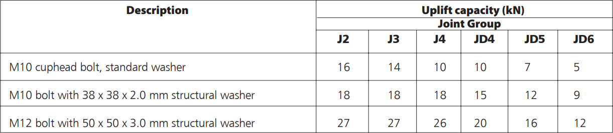
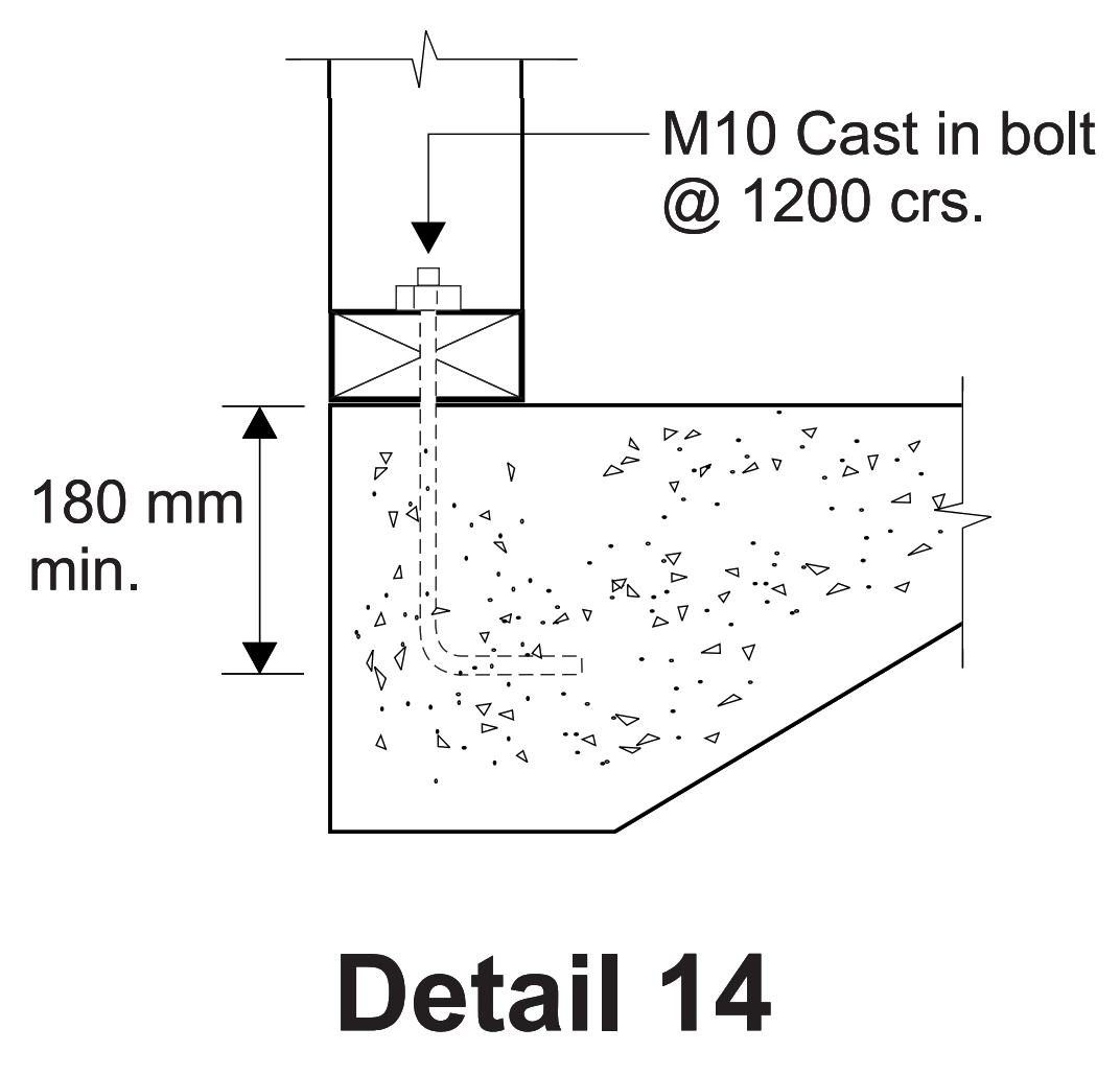
Figure 1: M10 and M12 bolts for bottom plates
The limit state design uplift capacity of masonry anchors shall be the lesser of the manufacturers design capacities and the above values provided the net bearing area under the head of the fastener is not less than the net bearing area of the above washers.
Based in WoodSolutions AS 1684 User Guide 9, 2012. All references have been updated to the 2021 version of AS 1684
Part of the intent of the changes that were made to bracing wall bottom plate fixingsin Amendment 4 to AS 1684, were to remove inconsistencies and anomalies between Part 2/3 and Part 4. Prior to the amendments, Part 4 permitted lesser bottom plate fixings for some bracing walls.
Unfortunately, the correction in Parts 2 and 3 for one hardboard bracing wall system, (Table 8.18, Item (I)) was overlooked. The correction in Part 4 was however implemented. For bracing walls rated up to 3.4 kN/m in Part 2 and Part 3, the fixing of the bottom plate to floor frame or slab, was amended to require nominal fixing only.
Until formal amendments can be processed through the Standards Australia AS 1684 Committee, it is recommended that hardboard bracing in accordance with Part 2 Table 8.18 Item (I) and Part 3 Table 8.18 Item (I) be accepted as requiring the bottom plates to be nominally fixed to the floor frame or slab (see AS 1684 Table 9.4).
This will then reflect the intended changes to Parts 2, 3 and 4.
Based in WoodSolutions AS 1684 User Guide 10, 2012. All references have been updated to the 2021 version of AS 1684
AS 1684 Section 8 requires permanent bracing to be provided to enable the roof, wall and floor framework to resist horizontal forces applied to the building (racking forces). Appropriate connection is also to be provided to transfer these forces through the framework and sub-floorstructure to the building'sfoundation (ground). Where required, bracing within the building will normally occur in vertical planes and be incorporated in walls or sub-floor supports and be distributed evenly throughout. Where buildings are more than one storey in height, wall bracing will be required to be designed for each storey.
Wind produces horizontal loads on buildings that must be transmitted through the structure to the foundation. In a conventionally constructed house these loads are transmitted to the ground by a complex interaction between the walls, ceiling/roof structure and floor structure. See Figure 1:
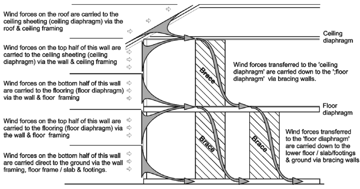
Figure 1: Horizontal Wind Forces (Racking Forces)
The ceiling and floor form large horizontal diaphragms which play an important role in distributing horizontal wind forces to bracing walls. Most walls also rely on support from the ceiling or floor diaphragm to prevent them blowing over. See Figure 2. The wind forces are transmitted to the ceiling diaphragm from the walls and also the roof. They are then transferred through the ceiling diaphragm to the bracing walls that transmit them to the floor structure, footings and then into the ground. The role that the ceiling plays in the overall structural integrity of a house is very important. For the ceiling diaphragm to work properly, the ceiling sheeting must have direct fixing to the roof/ceiling framing.
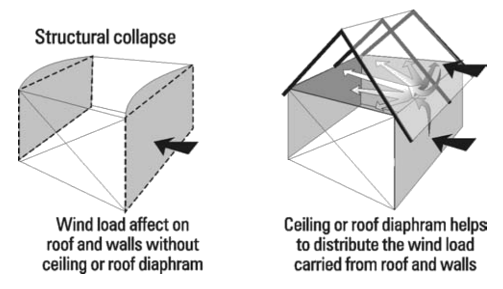
Figure 2: Horizontal Diaphragms
Ceiling battens, if used, must be fixed solidly to the roof/ceiling framing. If the ceiling is to be a suspended system or the battens are not fixed solidly to the roof framing, such as a metal furring channel fixed with a clip system, then alternate methods of distributing the loads must be found. This normally will require engineering advice. Another factor that will affect the ability of the ceiling diaphragm to distribute the wind loads is the depth of the ceiling diaphragm. A shallow diaphragm will not distribute the wind loads over a great distance whereas a deeper diaphragm will transfer loads further. See Figure 3.
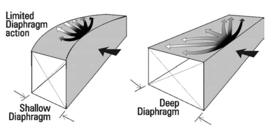
Figure 3: Effect of Ceiling/Floor Diaphragm Depth
For this reason the spacing of bracing walls in AS1684 is limited. For Single or Upper Storey, the spacing of bracing walls in N1 and N2 wind classifications is limited to 9000 mm maximum and in all other wind classifications, it is limited by the diaphragm depth and the roof pitch as per Clause 8.3.6.7. It should be noted that the higher the wind speed, the closer the spacing of bracing walls for the same roof pitch and ceiling diaphragm depth. The final link in the chain is to transfer horizontal racking forces to the floor frame, slab and foundations by connecting the bracing walls to the horizontal diaphragms both at their tops and at their bottoms. Refer to Section 5 for advice on fixing the top of Bracing Walls and Clauses 8.3.6.9 and 8.3.6.10 for fixing of top and bottom of bracing walls respectively.
AS 1684 Figure 8.1, Note 2, infers that ceiling diaphragms can be installed on the rake, as would be typical in cathedral or exposed raftered roof construction. See Figure 4. The code does not specify what the maximum roof slope for raked ceiling diaphragms is as it only refers to 'near horizontal' diaphragms. Raked ceiling diaphragms have however been permitted and have been used successfully in Australia for many years (including cyclonic areas) for roof slopes up to 35 degrees. As the Code is limited to a roof slope up to 35 degrees, Clause 1.6.7, it is recommended that this limit is also applicable to raked ceiling diaphragms.
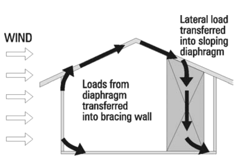
Figure 4: Raked Diaphragms
The ability of diaphragms to distribute horizontal racking forces is not considered to be affected by:
Diaphragms may also contain 'holes' that result from inclusion of stairwells or atriums providing the resulting discontinuity in the diaphragm is allowed for.
This can be achieved by determining the minimum net depth of the diaphragm, and using this depth for determination of the maximum spacing of bracing walls as per Clause 8.3.6.7 at either side of the opening.
Note: The spacing of bracing walls under the section/s of diaphragm that are full depth is still determined using the full depth of the diaphragm.
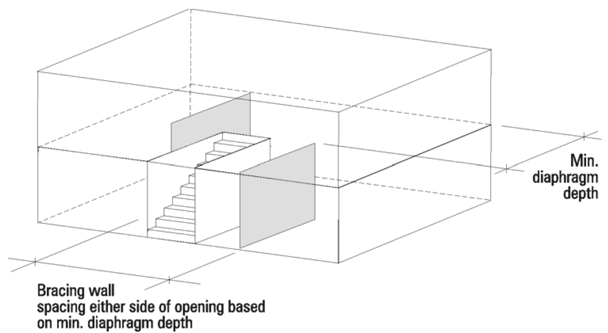
Figure 5: Holes in Diaphragms
If a horizontal diaphragm is considered to be simply, a very deep horizontal beam, it is logical that it could cantilever in a similar manner to any other beam. It is therefore recommended that diaphragms without discontinuities be permitted to cantilever up to 1/3 of their allowable spans (maximum bracing wall spacing) provided the non cantilevered section is at least 3 times the cantilever. See Figure 6.
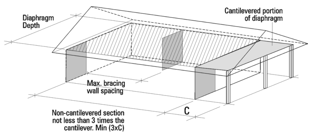
Figure 6: Cantilevered Diaphragms