Publications
TDG 21
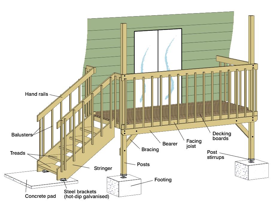
This guide outlines key design and construction considerations for light domestic timber decks for both raised and close to or on-ground timber decks that are exposed to the weather. It covers decks associated with Class 1 structures (such as detached houses, villas and townhouses) and Class 10 structures (such as garages, sheds and swimming pools) according to the National Construction Code (NCC) Volume 2. For the design and construction of decks for commercial, industrial or marine applications, or where a deck has to take heavier loads such as tiles, spas or even vehicles, a structural engineer must be consulted. Terms used in domestic deck design and construction are illustrated in Figure 1.

Figure 1: The anatomy of a deck
TDG 21
In all parts of Australia prone to bushfires, there are limitations on the use of timber in deck construction. This limit varies depending on the risk of bushfire attack and the elements of the deck under consideration.
Appendix A of this guide contains a list of common timber species used for timber decks and the maximum Bushfire Attack Level (BAL) that the species can be used for in a deck, in accordance with AS 3959 Construction of buildings in bushfire-prone areas.
Refer to WoodSolutions Technical Design Guide #4: Building with Timber in Bushfire-prone Areas for further information. It also should be noted that South Australia and NSW have some different requirements that need to be followed in those states.
The National Construction Code includes requirements for decks. The decks must be:
Primary building elements include framing members, floor (decking boards), stairways and ramps, i.e. elements that take part of the building load.
Where the installation of a termite barrier according to AS 3660.1 is chosen as the method to provide protection, AS 3660.1 requires attachments to buildings, such as decks, to be separated at least 25 mm from the building. Where this can’t be achieved, the termite barrier must be extended to include the deck.
Termite protection can be achieved by placing all posts that support the deck framing on galvanised metal stirrups that have at least 75 mm clearance above the finished ground level (Figure 2).
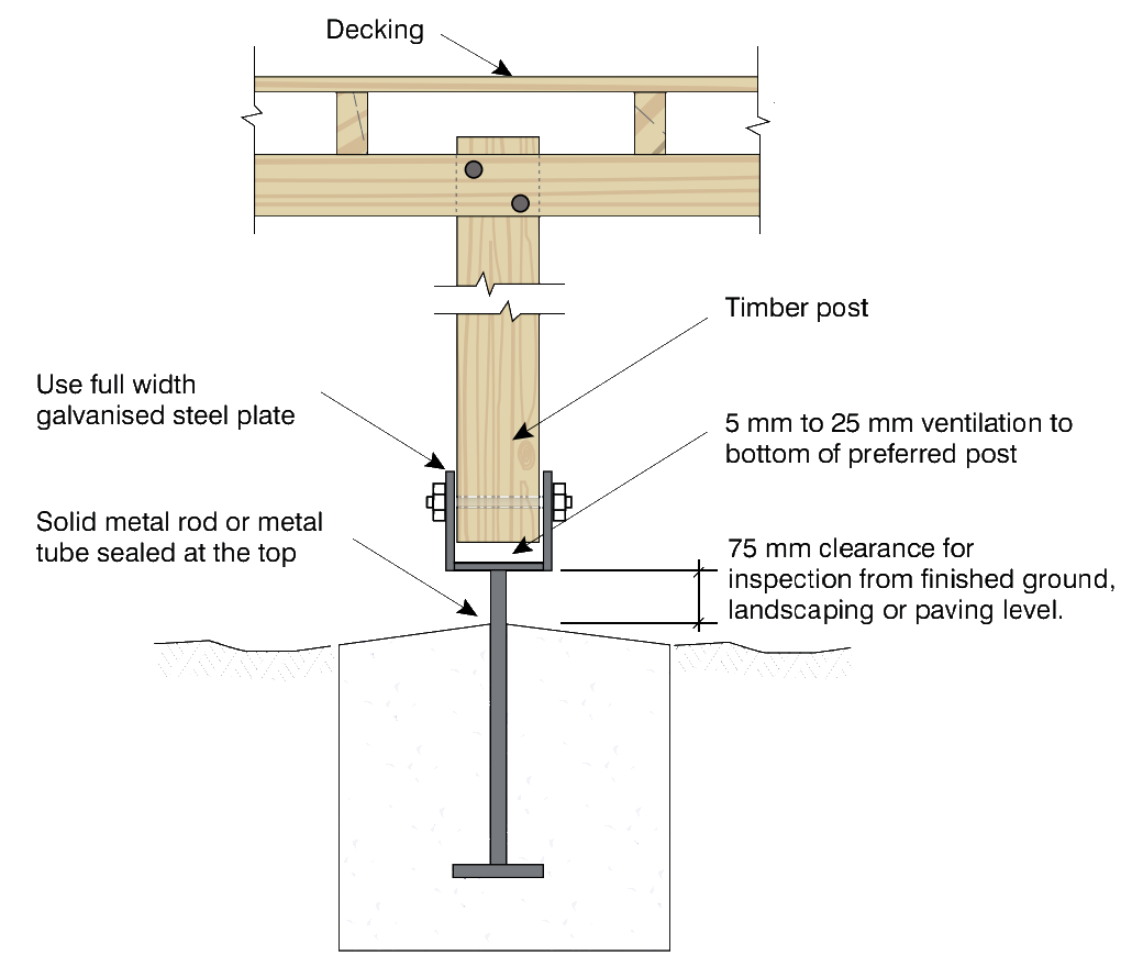
Figure 2: Termite protection on a timber decking post
Alternative deck supports include metal posts or brick piers. Where they are used, a termite cap can be placed between the pier and the bearer. Refer to Figure 3 for metal posts and brick pier supports.
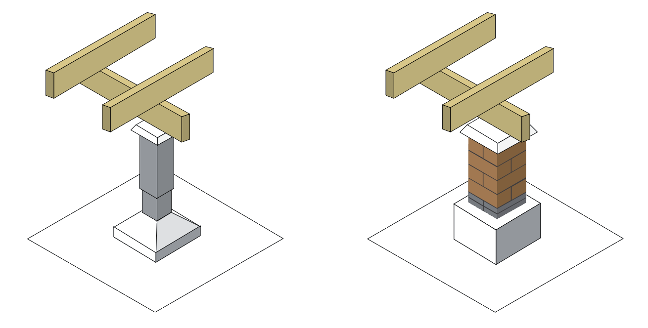
Figure 3: Deck supports, metal post or brick piers
Where engaged brick piers to the external wall are used to support bearers in addition to the termite cap, AS 3660.1 requires the bearer and joist of the deck to provide a gap of 25 mm between the wood surface and the building envelope (Figure 4). Again this is to ensure adequate termite inspection can take place.
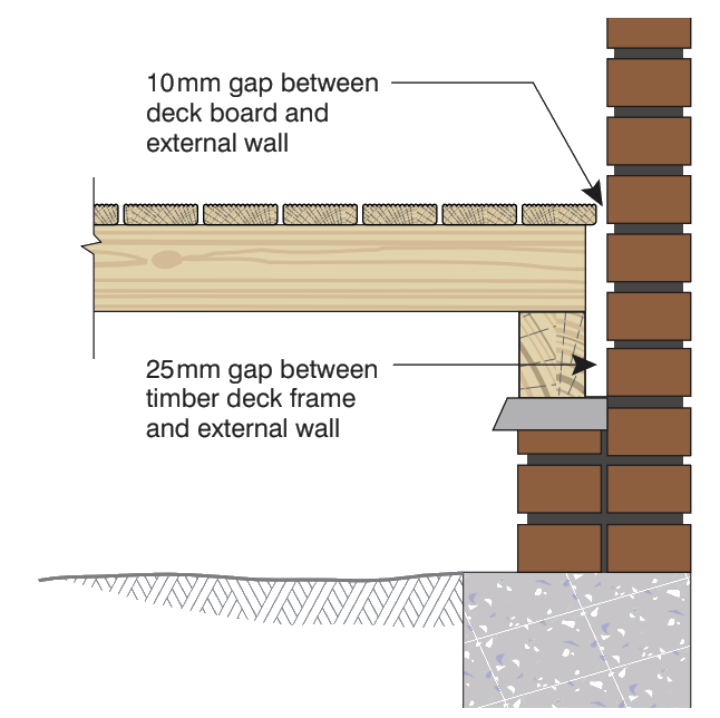
Figure 4: Requisite gaps between the wood surface and the building envelope
A good design technique is one that makes the inspection for termites easier, irrespective of what termite prevention method is employed to comply with the NCC. One method is having the decking boards that are parallel to the house envelop screwed instead of nailed, which allows easy and regular inspection without causing damage to the decking boards (Figure 5).
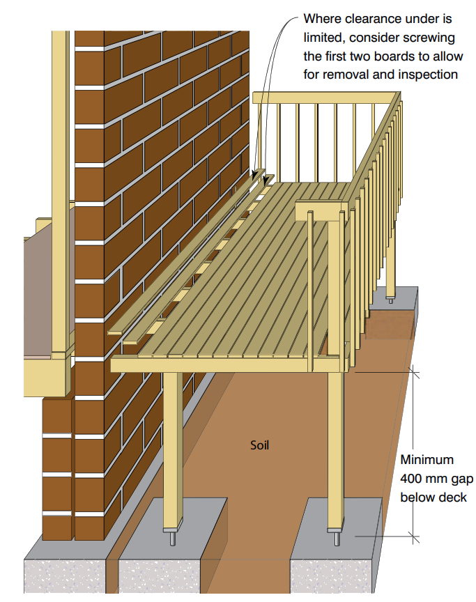
Figure 5: Parallel boards to the house envelope screwed, allowing for inspection
The following requirements for timber framing of a deck are based on the Australian Standard AS 1684 Residential Timber-framed Construction.
Bearers and joists come in a variety of stress grades, timber types and sizes and their availability will vary from one region to the next. Before designing a deck, check availability with local suppliers of timber.
The available stress grades in unseasoned hardwood are usually F11 and F14, while seasoned hardwoods are available in F17 or F27 stress grades. Treated softwoods are predominately available in F7 stress grade; however, F5 and MGP10 are available in some regions.
For deck floors greater than 1,000 mm above the finished ground level, bearer sizes can be found in the span Table 49 in AS 1684. For deck floors less than or equal to 1,000 mm greater than the finished ground level, span Table 5 in AS 1684 can be used. Both these tables assume a minimum end bearing of 50 mm by bearer width, and intermediate bearing of 100 mm by bearer width for continuous bearers.
To avoid splitting when receiving nails or screws from the placement of decking boards, joists that are at least 45 mm wide (seasoned hardwood and treated softwood) or 50 mm wide (unseasoned hardwood) are recommended. This is particularly relevant where decking boards abut over the joist as the fixings can be placed further from the board’s end. For deck floors greater than 1,000 mm above the finished ground level, joist sizes can be found in span Table 50 in AS 1684. For deck floors less than or equal to 1,000 mm greater than the finished ground level, Table 6 in AS 1684 can be used. Joists of 35 mm or 38 mm wide are only suitable where proprietary deck fixings are fixed to the side of joists.
The recommended timber sizes for the bearers and joists are for when timber only decking boards are being used. Where the deck is to be tiled, or a spa or hot tub is built into a deck, the sizes in AS 1684 are not applicable. In these circumstances, advice should be sought from a structural engineer. Engineered timber products used in exterior applications have a varying degree of performance and are dependent on the type of engineered wood product, level of exposure and projection methods employed. Individual manufacturers of engineered wood products should be consulted prior to considering the use of engineered wood products in deck construction.
Placing a layer of 110 mm malthoid dampcourse or proprietary protection strip on top of a joist will increase its service life (Figure 6).
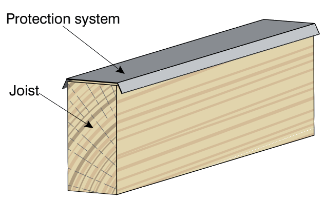
Figure 6: Protection system over a joist to increase service life
The joints between posts, bearers and joists need to be able to transfer load efficiently through the structure – refer to AS 1684 for the design of these elements. Where possible, bearers and joists should be long lengths and continuous, spanning over at least three supports.
Where joints in bearers are required, they must occur over supports and provide an adequate bearing for each bearer. Joints in joists must be made over a bearer and have a minimum of 30 mm of bearing for each joist. Figure 7 illustrates methods to join joists, where they are required to be in line. Scarf or butt joints can be used with a minimum of 30 mm of bearing for each joist.
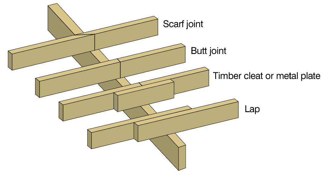
Figure 7: Joints in deck joists
All connections should be of sufficient durability. All framing bolts, screws, nails, and other hardware should be hot-dipped galvanised or stainless steel. Electroplated fasteners are not suitable due to early breakdown of the plating. Fixings within the splash zones (minimum 1.0 m from pool edge) of swimming pools or in coastal zones (within 1 km of the coast) must be stainless steel. Fixings for preservative-treated decking boards should be hot-dipped galvanised, stainless steel or with a coating approved for use with treated timber decking.
Refer to WoodSolutions Design Guide #5: Timber Service Life Design – Design Guide for Durability for further information on the estimated service life of connectors.
Due to moisture potentially being trapped at the interface of crossing timber members, e.g. bearer and post connections, a timber sealer should be used between the interfacing elements. Timber washers need to be appropriately sized (Table 1).
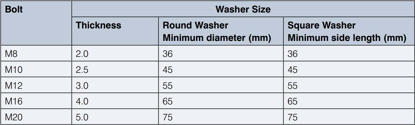
Table 1: Timber washer selection guide coach screws or bolts. Source: AS1720.1
There are three main types of decking board profiles available: plain, pencil round and ribbed/reeded (Figure 8).
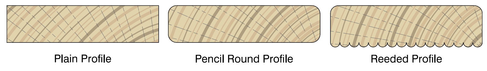
Figure 8: Decking board profiles
Plain profile decking is not common as the square edges of the boards are more prone to splintering. Pencil Round has significantly less chance of splintering compared to plain boards and is the most common decking board available. Ribbed (or reeded) board profile can be used face up or down. Where ribbed boards are used face up, care should be taken in moist areas that the boards are kept free of mould and moss build-up that can make them slippery.
Decking boards are available in various widths. For 19 mm thick Australian species boards, the widths that are usually available are 64 mm and 86 mm. Imported hardwood decking species are generally available in 70 mm or 90 mm widths. Other widths are available, but consultation with suppliers regarding availability is required before specifying.
In all cases, it is recommended that boards with a narrow width are selected because it is easier for water to drain through the deck. Where wider boards are selected, they will need to be thicker to reduce the possibility of cupping developing.
Tongue and grooved timber, plywood or particleboard sheet flooring products are not recommended for use as decking in weather-exposed situations.
Decking boards have no stress grade requirements, unlike joists and bearers and other framing material, that is assigned a stress grade. Instead of this, decking boards have to meet an appearance grade, which are limits on knots, holes, gum pockets, splits, shakes, wane, and want. Hardwood, cypress and softwood have their own appearance grading standard and are listed in Table 2. Generally, a product that is described as Select will have fewer timber features than a product described as Medium Feature Grade or Standard. In all appearance grades, the decking board will have timber features included within.
The Australian Standard AS 1684 provides a relationship between the various thickness of the board, the appearance grade, and the maximum joist spacing (see Table 2).
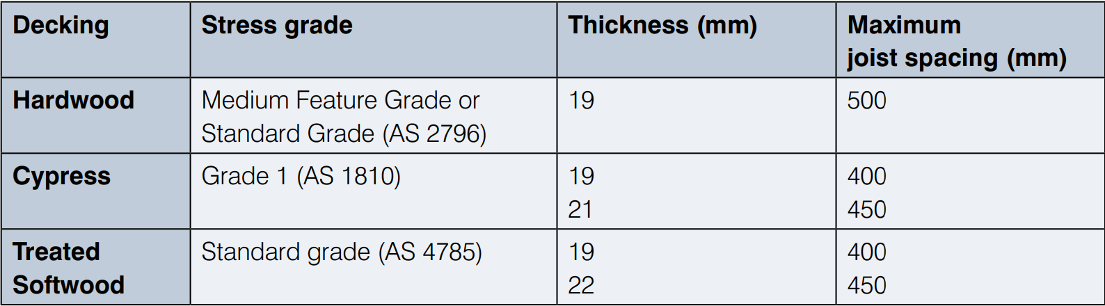
Table 2: Maximum joist spacing for various decking boards. Source: AS 1684
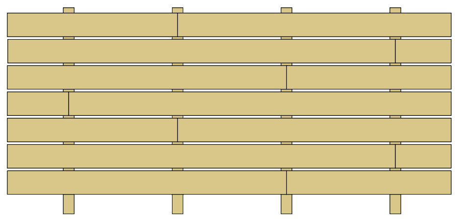
Figure 9: Illustration of staggered decking boards
Deck boards can be laid in various directions to add style to the project; Figure 10 shows various decking patterns. Care is required to ensure that decking boards that are not perpendicular to the joists do not span further than the maximum joist spacing allowed (see Table 2). For example, 19 mm. Standard grade hardwood decking boards at 45 degrees to the joists will require the joist spaced at 350 mm to maintain the maximum allowable span of 500 mm.
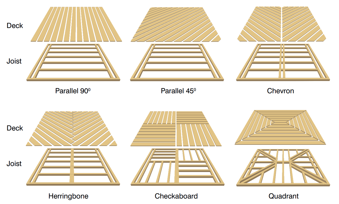
Figure 10: Decking board patterns
Decking boards should also be kept 10 mm clear of the building wall to allow a drainage gap between the building wall and the boards (Figure 4 above).
Each board must be fixed at each joist with at least two nails, which should be finished flush with the top of the boards (rather than punched) to prevent moisture being trapped. Where the fixing occurs, other than at the ends of the board, nails should be staggered across the joist to avoid the possibility of cracks caused by moisture movement in the decking (Figure 12).
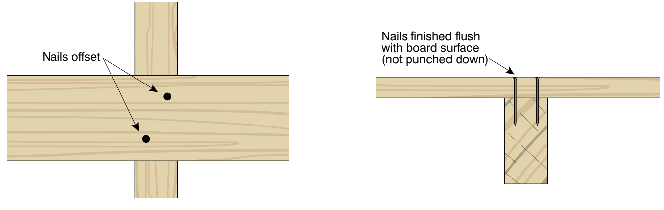
Figure 12: Illustration of nail fixing in timber decking
To obtain a tight fit at joints for abutting boards, a slight under-cut is recommended (Figure 13). To reduce the splitting of the decking board, nails or screws must be kept a minimum of 12 mm from edges and the board’s end and holes predrilled. The drilled nail holes should be 80% of the nail diameter.
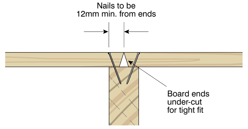
Figure 13: Nailing at board ends
Table 3 describes the minimum hand-driven nails that can be used for decking up to 22 mm thick and the deck joists.
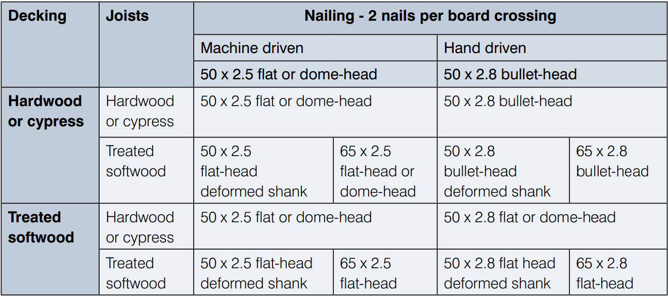
Table 3: Minimum hand-driven nail size for various timber species decking and joist combinations
Machine-driven nail properties usually vary between nailing gun manufacturers and are considered proprietary to the manufacture. Machine-driven nails can be used as long as the nail has the same capacity as the hand-driven nails detailed in Table 3. T-nails should not be used. Care is required when using machines to ensure the nail head is not driven below the surface of the board.
As is the case for machine-driven nails, screw requirements are not referenced in AS 1684. The principles described above for machine nails should be followed for screws. Types of screws are usually proprietary information and reference to the manufacturer’s specification is required.
Screws normally used for fixing timber decks are not suitable for fixing timber decking to steel joists. This is due to the seasonal and differential expansion and contraction of timber decking against the steel substructure that may cause the screws to fail in shear. It is recommended that a timber batten is affixed above or beside the steel joist, so the decking board is nailed or screwed to this timber batten. The size of any timber batten must allow adequate fixing for the decking to batten as well as the batten to the steel joist.
There are a number of proprietary systems available that fix the decking at the side of the board. Figure 14 shows one system. Most systems require a groove into the side of the decking for fixings while some use spikes. In all cases, the fixing systems are proprietary and manufacturers’ recommendations must be followed.
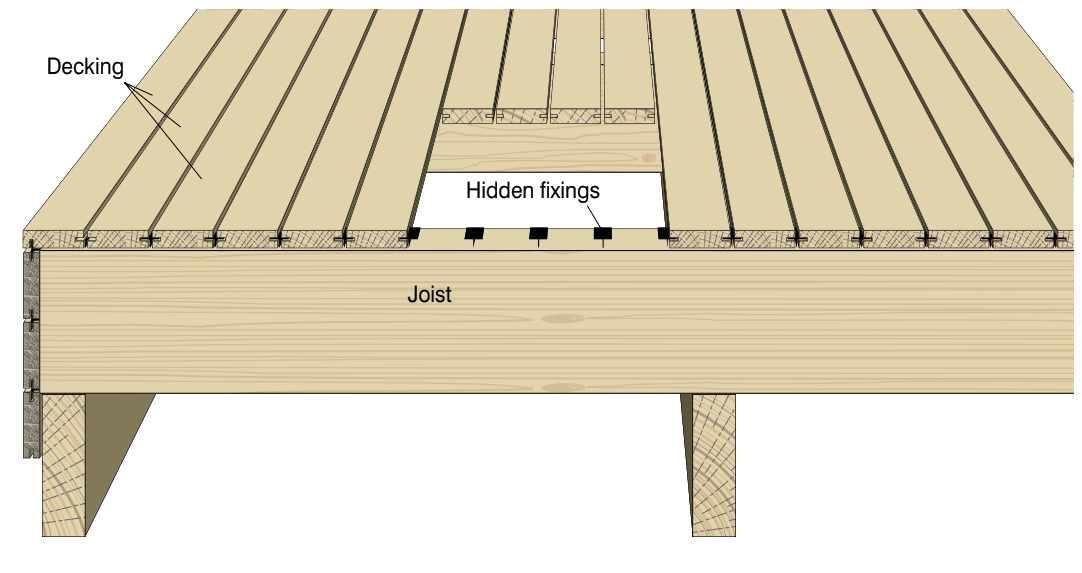
Figure 14: Hidden timber deck fixings
A common source of deck failure has been the fixing of decks to an existing or new building. It is recommended that the deck be self-supporting, i.e. on its own posts or piers, and not connected to the building’s external wall or subfloor framing.
Where this is not possible, the NCC has specific requirements for fixing decking to existing or new buildings. These requirements are for a particular situation, and if it is not possible to meet the NCC requirements, the design should be carried out by a structural engineer.
Care is also required in the way decks interface with the building’s exterior fabric, as water ingress into the house may develop at this crossing point. Flashing is one way to provide a barrier to prevent moisture from entering the house. Also, consideration is required to maintain the appropriate performance of other external wall function such as fire resistance, bushfire protection, external sound insulation and thermal insulation.
It is important that a suitable finish is applied and maintained to protect the surface of the timber from weathering and to maintain an attractive appearance. This protective finish of the timber surface will reduce the effects of weathering of any timber (treated or untreated) in an exposed situation. From a durability perspective, the main function of the finish is to slow down the rate at which the timber will take up or lose moisture. By slowing that rate down, the severity of any checking on the surface of the timber is considerably reduced. The finish should contain a fungicide to prevent mould from growing on any sugars or starches that may be in the finish.
Translucent coatings and stains are typically a combination of film-forming and penetrating coatings with added preservatives, fungicides and colourants. The degree of film formation and penetration varies with product and manufacturer. At a minimum, a protective finish should be applied to all surfaces (including any freshly cut ends) of each decking board, preferably before fixing to the joists. A protective finish includes products that penetrate the surface of the timber and products that provide a film or coating to the surface of the timber.
Further information on timber finishes can be found in the guide Finishing Timber Externally.
Where there is a risk of the deck becoming slippery when wet, especially if it is not kept clean and brushed regularly, the slip resistance of the decking boards can be increased by the choice of finishes or the addition of slip-resistant strips.
Slip-resistant finishes can be achieved by adding a slip-resistant additive to the deck finishing product. Some coating manufactures have products with anti-slip particles already included, while others have particles that can be added to standard coating products. Refer to the coating product manufacture for more information.
The recommended durability of the timber for deck sub-structure and decking boards is in Section B of this guide. In all cases, either a recommended natural durability class or preservative-treated timber hazard level is given.
There are two natural durability classes used in this guide: ‘above-ground’ (AG) and ‘in-ground’ (IG) and they refer to the heartwood of the timber only. The sapwood of all timber species is considered non-durable when exposed to the weather. A number of Australian Standards list the above-ground and in-ground natural durability class for various timbers and these Standards are:
More information on timber durability can be found in:
The natural durability class of many imported timbers can also be found in the Australian Standards referenced above.
Where there is no durability class given for a timber species, an indicator of performance can be found for a number of timber species from the paper; Natural Durability of Wood: A Worldwide Checklist of Species, Scheffer and Morrell, 1998. Note, the durability classes quoted in this publication, do not correspond with Australia’s timber durability system.
Specifiers in Queensland must also refer to the Construction Timber in Queensland guide available from the Queensland Department of Agriculture Fishery and Forestry.
Australian Standard AS 1604 Timber – Preservative-treated – Sawn and round defines the retention rates for various timber preservatives for different exposures and hazard levels.
Handrail or decking boards treated with the preservative Copper Chrome Arsenate (CCA) are not allowed to be used in areas where children could come into frequent or intimate contact with it. CCA treated timber can be used in other locations of the deck, such as sub-floor framing, roof rafters, and so on. Timber treated with other preservatives such as ACQ (alkaline copper quaternary), copper azole or LOSP (light organic solvent preservatives) can be used as handrails and decking boards.
Timber treated with LOSPs is not suitable for in-ground use (H4 or H5 hazard level) and timber treated for additional resistance to termites (H2f, H2s and H2 hazard level) is not suitable for use in weather exposed applications.
If the deck is more than one metre off the ground, handrails or balustrades are required. The choice of appropriate handrails and balustrades will depend on the design and application and even location in relation to other structures. For example, balustrades for decks next to a swimming pool vary from balustrades required in the NCC for fall protection. Further information can be found in WoodSolutions Technical Design Guide #8: Stairs, Balustrades and Handrails Class 1 Buildings – Construction.
Timber is a natural product and, as deck timbers weather, small cracks (or checks) are likely to appear on the surface of the boards. These cracks are caused by the intermittent wetting and drying of the wood. They are part of the character of wood and have no structural effect. This natural ageing process can be slowed by the use of finishes, as discussed above, which reduce moisture movements in timber.
All decks will benefit from regular maintenance, otherwise, the decking boards will discolour, and the surface will become rough and prone to splinters. A poorly maintained deck is also susceptible to mould, which can make the surface slippery or reduce the service life of the decking boards. The deck should be cleaned regularly. When cleaning the deck, avoid hosing it down; use a broom or a blower instead.
Pot plants or other items that are not moved regularly should be elevated off the deck. Pot plants should be placed in drip trays. To minimise uneven weathering of the deck, all items should be moved regularly.
At least once a year, or as indicated by the coating manufacturer, the deck should be thoroughly cleaned, and resealed or stained. The process involves the removal of dirt, algae, moss and other organic matter.
Clean the deck by hosing it down with an appropriate deck-cleaning solution. The deck should then be scrubbed and rinsed. During this process, check for loose boards and nails or screws that stick up and make any necessary repairs. Also, examine all areas where deck boards come into contact with any joists or any point that comes into contact with the ground. These areas are particularly susceptible to moisture damage.
Allow the deck to dry and reseal it with the sealer or stain originally applied. Where a different finish is used to the original finish, check with the manufacturer about using different types of sealers or stains, as mixing them may prevent adhesion of the new coating.
Most hardwood timber species contain water-soluble extractives that provide colour and some natural decay resistance to the timber. Water-soluble extractives may be leached to the surface of the timber whenever moisture leaves the timber. Because the discolouration is water-soluble, it can be washed to other surfaces and may leave an unsightly stain that can be difficult to remove from brickwork, concrete or any paving underneath the deck that is not sealed. To lessen the likelihood of such extractives bleeding and staining, use seasoned timber and apply a water-repellent finish to all surfaces, including any freshly cut ends.
Any iron filings that are not cleaned from the surface are likely to react with moisture and the timber extractives to create unsightly black staining on the timber. Avoid using any power tools on, near or above an uncovered deck that may deposit fine iron filings or dust on the timber surface. Particular care should be taken with cutting metal, masonry, brick or ceramics with an angle grinder. Cutting bricks or tiles with an angle grinder creates iron filings from the metal mesh that forms the base of the cutting disk. Storing or leaving metal on the deck for long periods of time may also cause tannin stain.
Some softwood timber species boards such as radiata and slash pine can be prone to resin bleed. Ideally, if a board shows obvious signs of resin bleed, it is preferable not to use that board or to cut out the affected area. If it has to be fixed in the deck, it should be fixed in a position where the resin bleed won’t be a problem. Sometimes it may not be obvious that a board is prone to resin bleed until after the finished deck has been exposed to a period of hot weather. In such circumstances, the resin can be cleaned up or the offending board replaced.
A raised timber deck is any timber deck where the decking boards are more than 400 mm above the finished ground (Figure 15). It is assumed there is appropriate drainage available for water and adequate cross-flow ventilation underneath the deck. Adequate cross-flow ventilation for decks is regarded as the same as the minimum requirement for raised timber floors in houses. For the minimum cross-ventilation requirements, refer to the NCC.
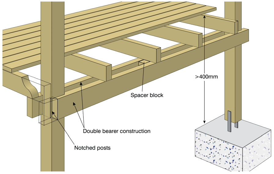
Figure 15: Raised timber deck
The sub-deck supports transfer horizontal and vertical loads into the ground, sometimes including uplift forces, particularly where decks are covered with a roof.
Footings for supporting posts are usually designed in two ways. The most common method is concrete footings with galvanised stirrups embedded or fixed in the footings to support the posts (Figure 16).
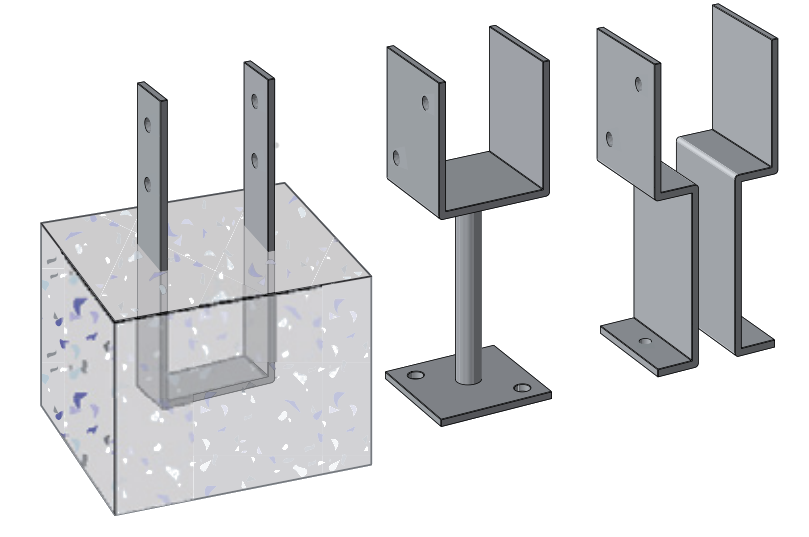
Figure 16: Proprietary metal stirrups
An alternative method is to support the deck post by embedding the post directly into the concrete footing. When this method is used, use no-fines concrete, have adequate concrete under the post and slope the top of concrete footing away from the post (Figure 17).
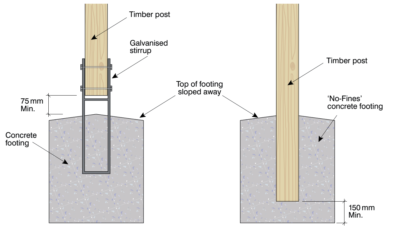
Figure 17: Post embedded into concrete footing
The design of footings is outlined in AS 2870 or AS 1684. Usually, the soil classification and expected loads on the deck are required to be known. Decks designed to AS 2870 and AS 1684 are for decks used for housing with average loads and ground conditions. If these conditions are not met (e.g. the deck needs to support a spa or the deck is to be tiled), the design needs to be considered by a structural engineer.
Unless the deck is entirely protected by a roof, the timber framing and boards will be exposed to the weather, so it is essential that the selected timber can provide a good service life in those conditions.
Timbers used above the ground (framing, boards and posts on stirrups) should be hardwoods rated above-ground natural durability Class 1 or 2 (plus sapwood removed or H3 treated) or if softwood is used, preservative-treated to at least H3 hazard level. Softwood timber that is treated to H2, H2F or H2S hazard level is not suitable for use in the construction of decks. Timber embedded in the ground (embedded posts) should be in-ground natural durability Class 1 or be preservative treated to H5 hazard level. Refer to Appendix A for a list of common timbers and their above-ground and in-ground natural durability ratings. Durability ratings only refer to the heartwood of the timber. Sapwood is not durable when exposed to the weather.
A wide variety of engineered wood products are now available on the market, such as glue-laminated timber, finger-jointed timber and LVL products. If these products are being considered, direct reference to specific manufacturer recommendations is required. In most cases, there are additional requirements or limits when these products are used in applications such as decks where they are exposed to the weather. Timber I-beams (treated or untreated) are not suitable for use in the construction of decks.
As described previously, posts are usually connected to concrete footings via a stirrup. They are generally preservative-treated softwood (H3 hazard level) or natural above-ground durability Class 1 or 2 timber species.
The span tables within AS 1684 have the required timber sizes for posts. These are dependent on the deck area, roof area (if any), post height and stress grade of the timber selected. Common crosssectional sizes for posts vary, but usually start at 88 mm and upwards. Minimum sizes for posts are also governed by the distance between the ground and the underside of the bearers. The maximum height of a deck above the ground for a given post dimension is 15 times the face width of the post.
Deck posts need to be braced and AS 1684 has various bracing methods. These methods are either cross-bracing between posts (Figure 18) or as a cantilever timber stump (Figure 19).
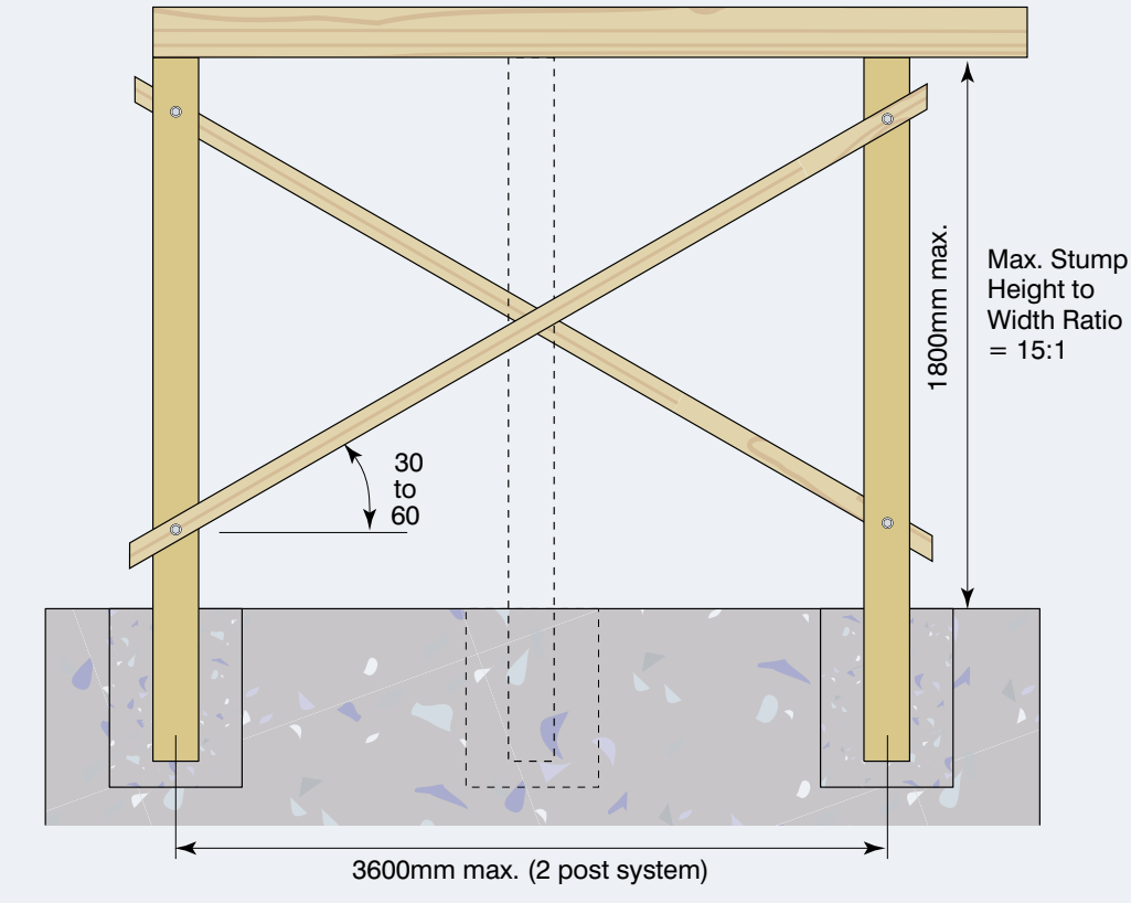
Figure 19: Braced timber posts
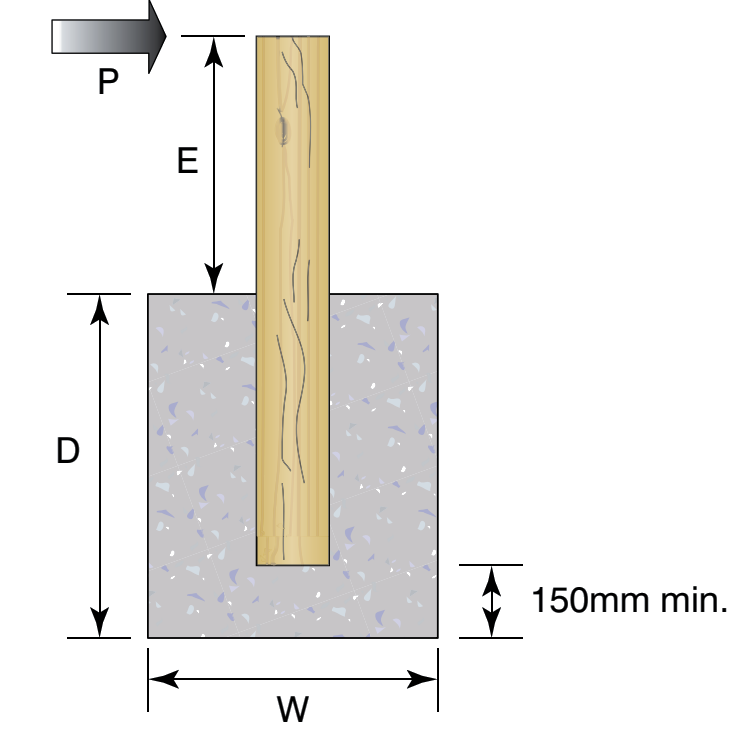
Figure 19: Cantilever timber stump
The purpose of spacing decking boards is to allow seasonal movement of the timber, so a gap is maintained to allow water to drain freely. The gap must not be so far apart that it forms a trip hazard. The size of the gap between the boards depends on:
A gap of 3 mm to 4 mm is ideal over the long term. Table 4 shows the recommended spacing at the time of decking board installation.
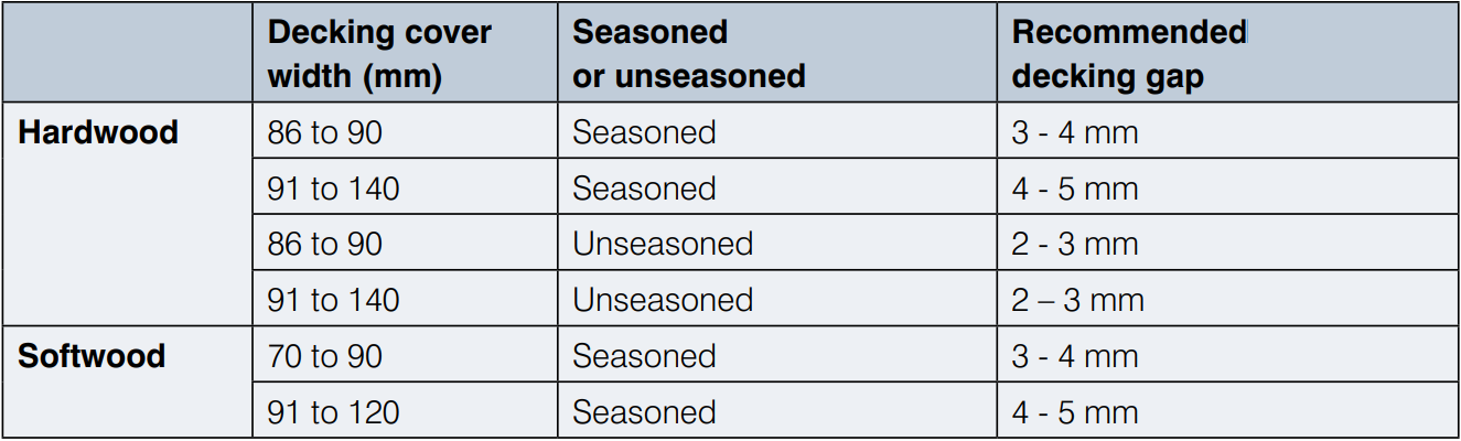
Table 4: Recommended decking gaps at installation
The Building Code of Australian has a new Deemed-to-Satisfy requirement for attaching decks to external walls of buildings. The scope of decks that are required to comply with this DTS is:
The waling plate is to be at least 190 x 45 mm or greater and be of stress grade MGP10 or F5 or higher.
The waling plate is to be fixed to the external wall with fixings placed at a maximum of 300 mm centres. Fixings can be M12 coach screws or 4.6/S M12 bolts with a 3 mm thick and 55 mm diameter washer. The coach screw is to have the screw part of the coach screw embed into the subfloor framing or external wall of the building for at least 96 mm (see Figure 20).
Fixings are to be hot-dipped galvanised or stainless steel if the building is located with 200 m of breaking surf. Fixings into the waling plate or other subfloor timber framing must not be located within 120 mm of the end or 60 mm from the top and bottom edge.
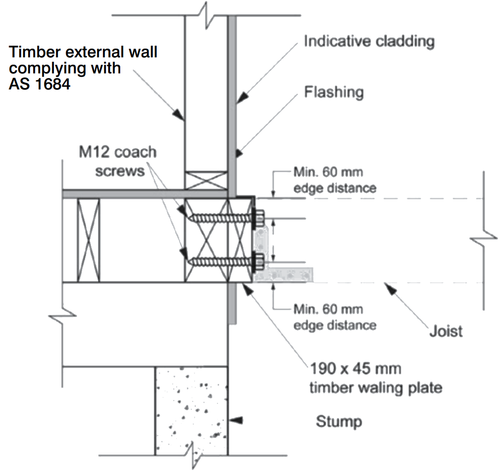
Figure 20: Fixing of a waling plate to an external wall
Where cladding is removed from the external wall, flashing must be provided in accordance with the BCA provision 3.10.6.3. Also, consideration is required to maintain the appropriate performance of other external wall function such as fire resistance, bushfire protection, external sound insulation and thermal insulation.
Where the decking surface is 1 m or more off the ground, the decking structure is to be braced. Bracing consist of a 30 x 0.8 mm thick steel strap, placed diagonally at an angle between 30 and 60 degrees to the waling plate. The steel strap is to be continuous and not span more than 4.0 m measured at right angles from the external wall (see Figure 21). The steel strap is to be installed either to the top side or the underside of the decking joists.
Fixings for the steel strap must be 50 x 3.15 hot-dipped galvanised flat head ring shank, or flat head deformed nails, fixed at every joist the steel strap crosses.
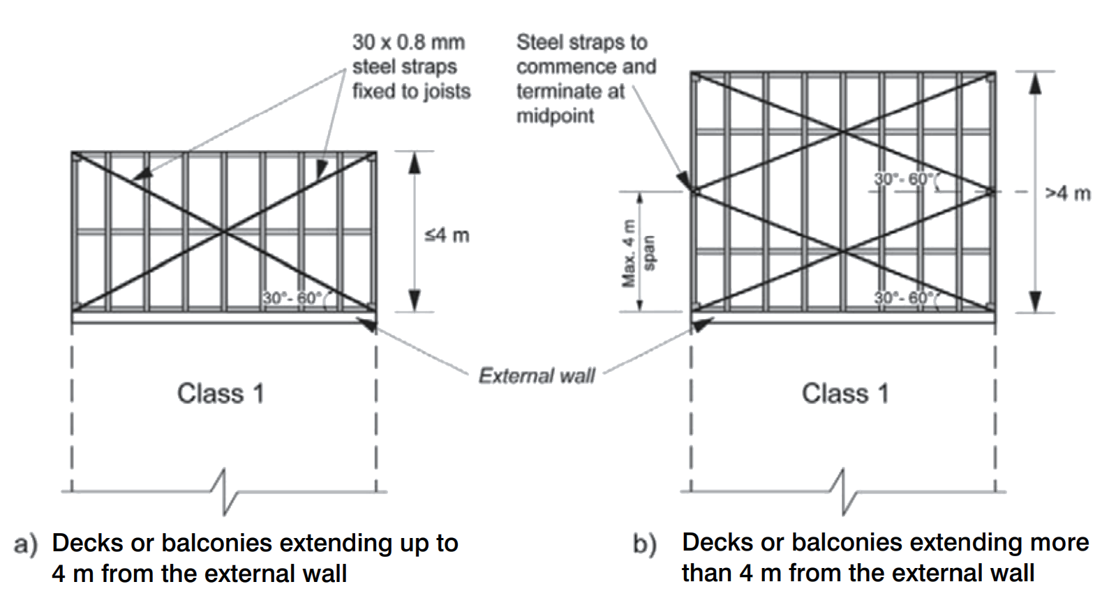
Figure 21: Bracing to deck's framing
When decking is less than 400 mm off the ground, additional consideration to ensure adequate performance and service life of the timber is required (Figure 22). This includes increased ventilation, sub-surface drainage, increased timber durability/preservative treatment and access for termite inspection and maintenance. Where any of the conditions described in the guide cannot be met, performance may be affected and the service life of the deck will be reduced.
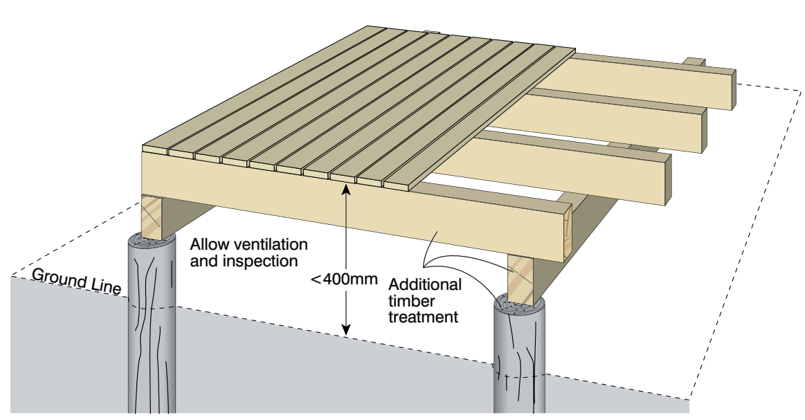
Figure 22: Timber deck close to the ground
It is important that the ground beneath the deck is completely cleared of all building rubbish, garden debris and obstructions to water or air movement. Water must not be able to pool under the deck and the ground must be sloped away from the foundations of the house or other nearby buildings. Agricultural drainage pipes may be required in some instances so water can properly flow away from beneath the deck.
Plastic sheeting acting as a waterproof membrane should be placed on the cleared ground. If timber bearers are to be placed directly on the ground, the plastic sheet should be covered with compacted gravel or sand to provide a solid base.
There are two main ways these can be arranged:
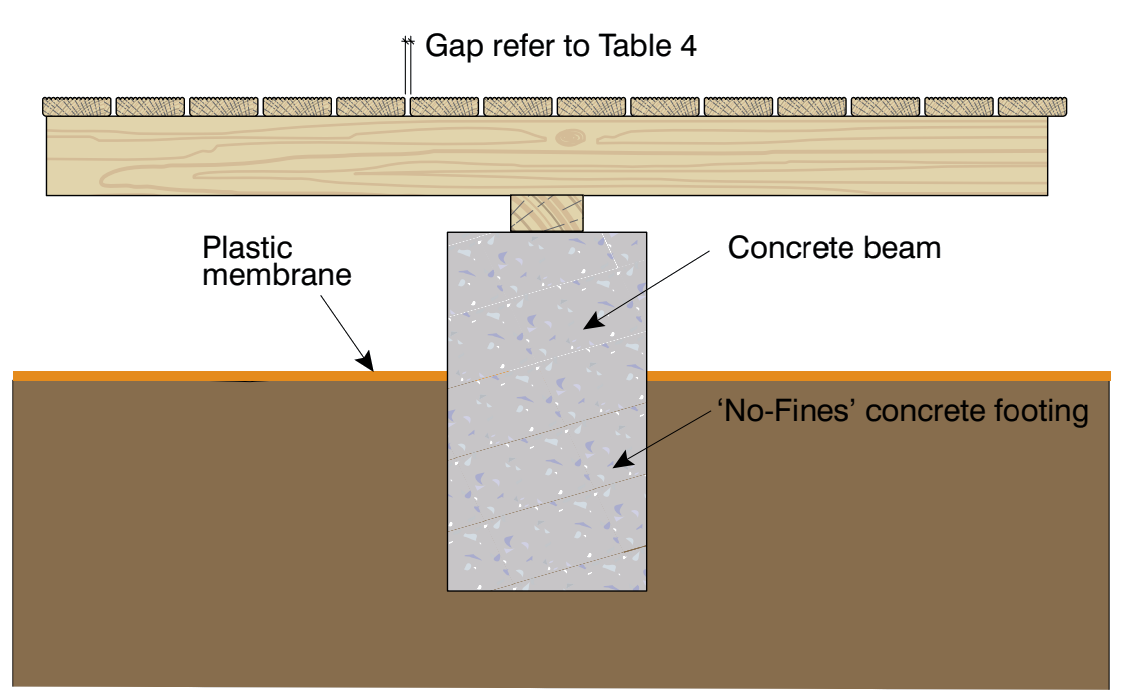
Figure 23: Concrete beam footing
Concrete foundations and bearers should be placed so they don’t restrict the flow or drainage of water. The perimeter of the deck should be kept open to allow for ventilation. Preferably, a decking system should be designed so it is panelised. The panels need to be sized so that they can be easily lifted to allow for easy maintenance and inspection.
Only termite-resistant timber should be used (see the section above) and there should be a gap between the house and deck of at least 40 mm to allow for pest inspection and air flow (see Figure 24).
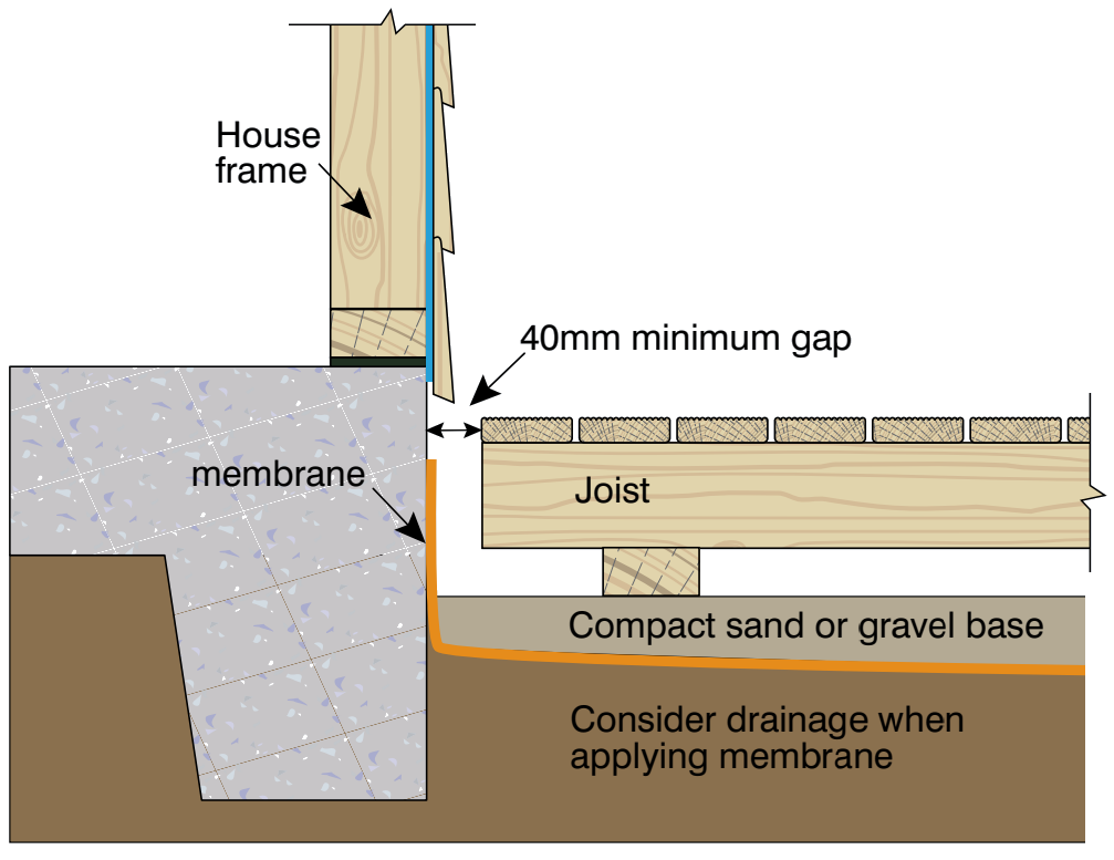
Figure 24: Bearer directly on to the ground
Timbers used close to or on the ground require additional durability as well as termite resistance. Framing timbers more than 150 mm above the ground should be termite resistant and above-ground durability Class 1 or 2 (plus sapwood removed or H3 treated) or softwood preservative treated to at least H3 hazard level. Framing timbers on the ground or lower than 150 mm should be termite resistant and in-ground durability Class 1 (plus sapwood removed or H4 treated) or preservative treated to H4 or better. Durability ratings refer to the heartwood only of the timber.
Decking boards should be termite resistant above-ground natural durability Class 1 or 2 (plus sapwood removed or H3 treated) or preservative treated to H3 or better. To reduce the likelihood of excessive movement and allow for more ventilation, the minimum width board should be selected.
The decking should be the minimum width available and have a minimum spacing between boards (long term) of 5 to 6 mm to allow water to flow between the boards and ensure adequate ventilation.
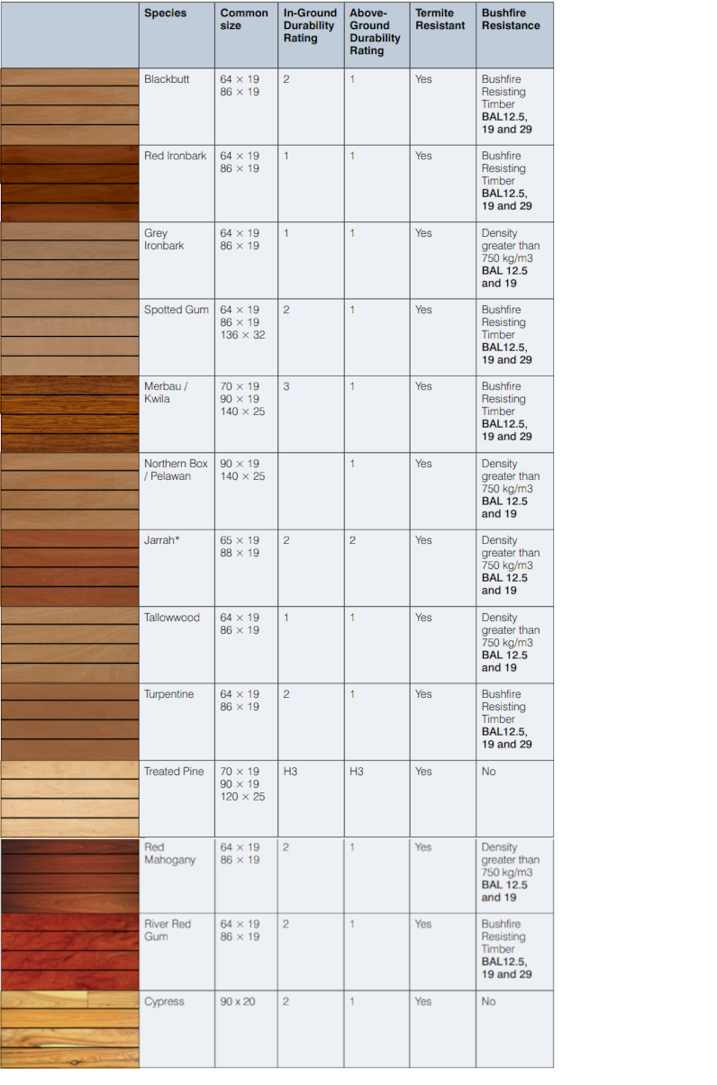
*Jarrah can be used in a BAL 29 situation under some circumstances.
Common problems to avoid when designing or building a deck:
Additionally, if a deck is built close to or on the ground, common problems include: