Publications
TBC


TBC
Mass timber has been used in Australian construction since 2012 in its modern engineered form, but timber mid-rise buildings have a much longer history. As the market for engineered mass timber grows, the insurance sector is developing its understanding of how these buildings perform, particularly in relation to fire, moisture, and long-term durability.
Insurance placement for mass timber projects can involve more detailed enquiry than for conventional concrete or steel-framed buildings, reflecting the relative novelty of modern engineered products rather than any inherent deficiency in the material. Insurers may request specific documentation on product compliance, construction methodology, moisture management, and fire precautions. Where this information is well-prepared and clearly presented, projects are more likely to achieve favourable coverage terms.
This page summarises the key themes from the WoodSolutions guide Insurance Risk Considerations in Mid-Rise Timber Construction, which addresses the common questions raised by insurers and brokers when assessing mass timber projects. It draws on guidance from Marsh, AXA XL, and the Construction Insurance Risk Engineers Group (CIREG), alongside Australian standards and WoodSolutions technical resources. The full guide is available as a downloadable resource.
While this guide focuses on mass timber, many of the principles discussed, particularly around moisture management, fire precautions, and site management, apply equally to non-residential lightweight timber frame construction.
The use of timber as a primary structural material in mid-rise buildings has a long history in Australia. During the late 19th and early 20th centuries, heavy timber construction was common across major cities, producing warehouses, factories, hotels, boarding houses, and other multi-storey buildings. These structures were built using large-section timber elements for posts, beams, and floor systems that align closely with today's definition of mass timber. Mid-rise mass timber buildings are not a new building typology.
Many of these buildings survive and remain in active use. In urban areas with high land values, older timber mid-rise structures have been redeveloped and converted for modern commercial, residential, and cultural purposes, often retaining heritage facades or structural elements while undergoing significant upgrades to meet current safety, accessibility, and energy efficiency standards. Two examples illustrate this trajectory:
The Walsh Bay Arts Precinct in Sydney repurposes a wharf structure, originally built with heavy timber framing, into a modern theatre and arts complex.
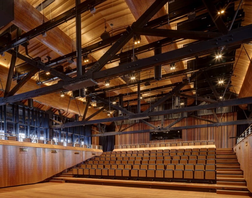
Figure 1: Walsh Bay Arts Precinct - repurposed wharf structure. Image credit: TDA
The Goldsbrough Mort building in Darling Harbour, another heavy timber structure, has been converted into a hotel. Both demonstrate the durability and adaptability of large-section timber construction across more than a century of service.
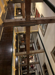
Figure 2: The Goldsbrough building - repurposed into a hotel, Darling Harbour. Image credit: TDA
Traditional construction methods in these buildings typically involved timber post and beam framing with load-bearing external masonry walls, and timber-framed interior walls and floors. One of the significant historical concerns with these older timber buildings was fire performance. With the introduction of modern fire safety measures including sprinkler systems, fire-rated construction materials, and improved building codes, the safety of these structures has been brought to contemporary standards. This long service history also means that loss data is available, providing insurers with a track record against which modern mass timber buildings can be contextualised.
The relevance for today's projects is straightforward: the structural use of large-section timber in multi-storey buildings is well-established. What has changed is the engineering and prefabrication: modern products such as CLT, glulam, and LVL offer greater dimensional consistency, verified structural properties, and enhanced prefabrication potential compared to the sawn heavy timber used historically. The insurance conversation should reflect this: modern mass timber buildings are a refinement of an established construction approach, supported by rigorous product standards, tested fire performance data, and detailed design guidance.
When seeking insurance coverage for a mass timber project, insurers will request specific information to assess risk. The questions they ask are well-established: frameworks published by Marsh and AXA XL set out common lines of enquiry, and the information required largely mirrors what a well-run project team would already be generating through normal design and construction documentation.
Understanding what insurers are looking for, and preparing this information early, can reduce the complexity of the placement process and support more favourable terms. The full guide addresses each insurer question in detail; this section provides an overview of the main areas of enquiry.
Insurers will need a comprehensive description of the project: building type (residential, commercial, industrial), number of storeys, gross floor area, construction timeline, and the specific mass timber products being used. Importantly, they will want to understand where mass timber is used within the building: as primary structure, as linings, or as non-load-bearing elements such as internal partition walls. This distinction matters because it shapes the risk profile.
The cost of the timber elements and their proportion of total project value is a standard request. Where a project comprises more than one building, costs should be separated between structures. When stating the cost of timber elements, it should be clearly defined whether this covers material only, material plus delivery, or material plus installation.
Costs that are often omitted such as shop detailing, taxes or tariffs on imported timber, and storage, should be explicitly included or stated as excluded. In the absence of a standardised cost definition, it is recommended to express all costs associated with purchasing and delivering timber to the construction site, and making this clear in the documentation.
Insurers will want to know whether the project follows an NCC Performance Solution pathway, a Deemed-to-Satisfy pathway, or a combination of both for fire and structural design. This helps them assess whether the structure follows standard design principles or involves project-specific engineering. Whichever pathway is used, all supporting reports, drawings, product technical statements, and test results should be available. Gaps in this supporting documentation not only make insurance placement harder, they also create difficulty in demonstrating NCC compliance itself. Having the documentation in order serves both purposes.
Insurers assess the experience of the people delivering the project, not just the building itself. They will look for evidence that architects, engineers, and construction teams have prior mass timber project experience. The most effective way to present this is as a list of previous mass timber projects the key team members have worked on, ideally highlighting projects where multiple members of the current team have collaborated before. Project value, volume or weight of mass timber used, building type, height, and gross floor area are the useful data points.
For contractors and specialist installers, insurers may also request evidence of appropriate training and certification for workers handling and installing mass timber components, along with any quality control procedures. They are likely to ask about the insurance coverage history of the primary and subcontractors, including any previous claims related to mass timber construction.
A comprehensive sequencing program should be provided, detailing the overall build duration and (critically) the period during which structural timber is exposed to the elements before the building envelope is closed. Start and end dates for each phase (structure, envelope, fit-out) allow insurers to assess the window of greatest exposure to weather-related risk.
This section addresses how insurers assess whether the mass timber products themselves are fit for purpose. It is one of the areas where the Australian regulatory framework provides strong assurance, provided the documentation is in order.
A key indicator for insurers that a product is suitable for use is the supplier's compliance with the National Construction Code and relevant state or territory regulations. The NCC provides several tiers of evidence to support compliance, from CodeMark certification at the highest level through to test reports, engineer's certificates, and Product Technical Statements (PTS).
A PTS is often the minimum documentation requirement, but it is a critical document. It sets out where the product can be used, which NCC performance requirements it satisfies, and any limitations including applications where the product should not be used, and maintenance schedules. For insurance purposes, ensuring the product supplier maintains current compliance documentation is essential.
The PTS should address how the product complies with structural, fire, energy efficiency, and acoustic provisions of the NCC. Supporting evidence: test reports, opinions, and engineering calculations, underpins each compliance claim. For example, where a fire resistance level is stated for a particular construction detail, a corresponding test result or assessment should be available to support it.
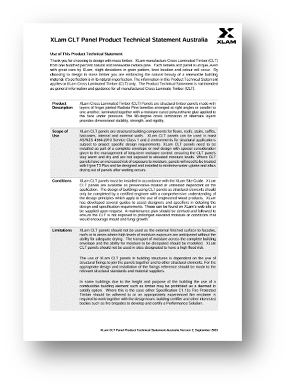
Figure 3: Example of a Product Technical Statement (XLam). Image credit: XLam
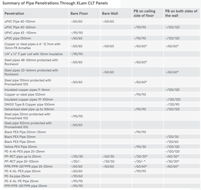
Figure 4: Example of demonstrated compliance: fire resistance levels for pipe penetrations through CLT, with each claim supported by test evidence. Image credit: XLam Australia & New Zealand Fire Design Guide
Insurers will want to know who manufactured the mass timber, what processes they use, where manufacturing takes place, and how the product is delivered to site. Where more than one manufacturer is involved (for example, CLT from one supplier and glulam from another), each should be identified along with the extent to which their product is used within the project.
Reference should be made to each manufacturer's design manuals (structural, acoustic, fire, and envelope), installation manuals, exclusions or limitations, material safety data sheets, and Product Technical Statements. Environmental product declarations and forestry certifications help verify environmental claims but also demonstrate supply chain rigour.
Beyond NCC compliance, recent legislation in New South Wales and Queensland holds every segment of the building supply chain accountable for the installation of compliant building systems. The NSW Building Legislation Amendment Bill 2023 and the Queensland Building and Construction Act 1991 require that individuals who design or handle building products are accountable for preventing safety or non-compliance risks, and that product information is accessible throughout the supply chain. This includes assessing suitability for intended use, identifying situations where a product should not be used, and outlining required maintenance. A current Product Technical Statement is the most direct way to satisfy these requirements.
For insurers, this legislative framework provides additional assurance that products entering a project have been assessed for compliance at each stage of the supply chain, not just at the point of manufacture.
Proper handling of mass timber from factory to installation is a recurring theme in insurer enquiries. Damage during transit or storage can compromise both the structural integrity and the visual quality of timber elements, particularly where exposed timber is part of the finished interior. The key principles are summarised here, with links to WoodSolutions Guide No. 53 (Moisture Management for Mass Timber Construction) for comprehensive protocols.
The chain of care begins at the manufacturing facility. Loading should follow the reverse order of installation to allow efficient unloading at site, and protective wrapping or coverings should be applied before transport. During transit, waterproof covers or enclosed trailers protect against rain and sun exposure, while soft materials placed between timber elements prevent friction damage. Ventilation during transport is important: insufficient airflow can lead to moisture accumulation and, in longer journeys, the early stages of fungal growth.
Route planning matters for mass timber. Many elements require special permits for oversized or overweight loads, and height restrictions at bridges and overpasses need to be checked. It is recommended to scheduling transport during off-peak hours and, where extra assurance is warranted, using GPS tracking and temperature and humidity sensors to monitor conditions in real time. Moisture indicator stickers which change colour irreversibly when exposed to water, offer a simple way to detect whether products have been compromised during transit.
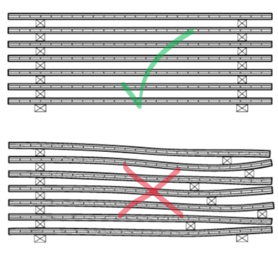
Figure 5: Stacking of mass timber do’s (above) and don’ts (below)
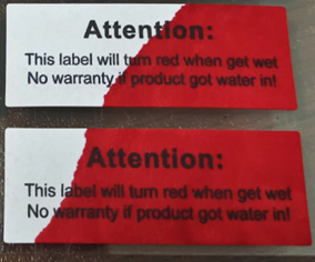
Figure 6: Moisture indicator stickers that provide visual indication of moisture exposure.
Whether stored at a temporary facility or on the construction site itself, mass timber should be elevated off the ground on raised platforms or dunnage, stacked using the manufacturer's recommended techniques to prevent warping or bowing, and covered with breathable, water-resistant coverings that protect from rain and sun while allowing air circulation. Staining timber members can be very difficult to reverse: slight marks from handling are generally accepted, but chains or forklift tongs applied directly to surfaces can cause damage that is costly to remediate, particularly on elements intended as finished surfaces.
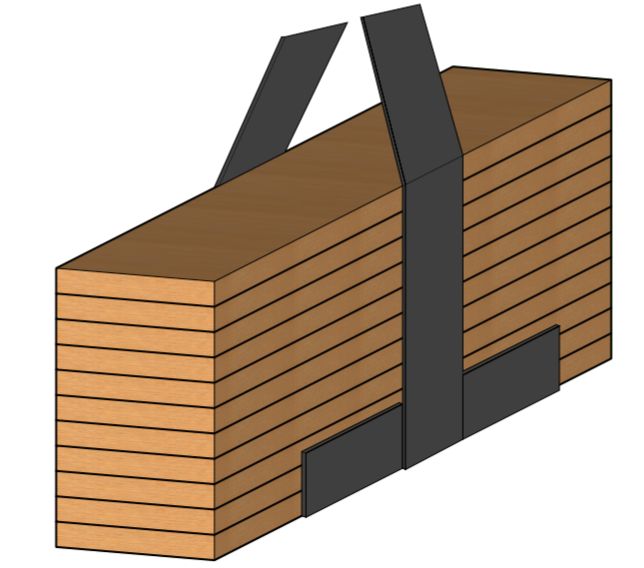
Figure 7: Correct support of slings and mass timber
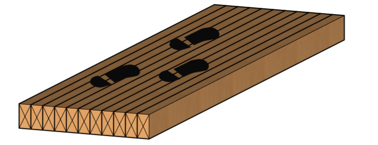
Figure 8: Avoid walking on mass timber surfaces, especially finished surfaces
Broad, clean lifting slings with edge protectors are recommended over chains or tongs. Walking on timber surfaces (particularly those that will be exposed in the finished building) should be avoided.
Just-in-time delivery, where elements arrive on site close to their installation date, is the most effective way to minimise storage exposure. Where this isn't feasible, a detailed plan for receiving materials should be established well before the first delivery. This includes determining how many loads can be received per day, where each load will be placed on site, how long materials will be stored, and the sequence in which they'll be needed. Each delivery should be documented on arrival: signing for materials, recording any damage on the Bill of Lading, noting shortages, and logging issues for resolution with the manufacturer.
WoodSolutions Guide No. 53 provides detailed protocols for both off-site and on-site storage of mass timber elements.
Beyond material handling, insurers will request information on several aspects of how the construction site itself is managed. These enquiries are not unique to mass timber, they reflect standard expectations for any major construction project. Documenting them clearly can support smoother insurance placement.
Separation distances
Insurers will want to understand the distances between the proposed mass timber structure and adjacent third-party properties, including neighbouring buildings, homes, businesses, and roadways. This allows them to assess exposure in the event of a fire or structural incident during construction.
Security
Whether 24-hour security will be provided, the frequency of patrols, availability of CCTV or other surveillance, and any additional protocols to protect the site and surrounding assets.
Waste management
How combustible waste (timber offcuts, packaging, protective wrapping) will be handled, stored, and disposed of. Accumulation of combustible waste on a timber construction site is a specific fire risk that insurers will scrutinise.
Emergency procedures
Fire suppression systems, evacuation plans, emergency response protocols, and the training and readiness of on-site personnel. Each state and territory fire service may have its own guidelines for construction sites, for example, the NSW Fire and Rescue Fire Safety Guideline for fire safety during construction work.
Figure 9: NSW Fire and Rescue Fire Safety Guideline - Fire Safety during construction work.
Quality management
Quality assurance and quality control procedures for the installation, handling, and maintenance of mass timber components, including testing or inspection protocols.
Construction fire risk management
Fire prevention strategies, commissioning of sprinklers, availability of fire extinguishers, and training of personnel. Insurers will specifically ask who is responsible for managing and auditing hot work permits, what the duration of those permits is, and whether fire watches are required after hot work.
The NCC itself requires fire precautions during construction for Class 2 to 9 buildings. Provision E1D16 mandates at least one suitable fire extinguisher on each storey adjacent to every required exit or temporary stairway. When a building under construction reaches an effective height of 12 metres, all required fire hydrants and fire hose reels must be operational on every storey covered by the roof or floor structure above, except the two topmost storeys.
Several international guides provide detailed information on fire precautions during timber construction.
Most of these site management considerations are not specific to mass timber. They represent standard practice for any substantial building project, and the development cost of these procedures can be amortised across multiple projects. Framing them as established protocol rather than special measures for timber construction is both accurate and helpful in discussions with insurers.
Moisture management cannot be emphasised enough. This reflects the insurance industry's experience: water escape incidents on construction sites have increased in both frequency and severity, and now rival fire as a source of construction losses across all building types. For mass timber specifically, moisture is a concern because excessive or prolonged wetting can lead to dimensional changes, surface staining, mould growth, and in sustained cases, degradation of structural properties and glue bond integrity.
The detailed protocols for managing moisture during mass timber construction are covered comprehensively by WoodSolutions Guide No. 53 and the Moisture Guide. This section focuses on the insurance-specific dimension: why insurers treat moisture as a priority risk, what documentation they expect, and the cost-benefit case for proactive management.
The Construction Insurance Risk Engineers Group (CIREG), a leading authority in the UK construction insurance industry, has published guidance on water escape risks that is now widely referenced by insurers assessing projects in Australia. Their key finding is that many of the largest water-related losses occur in the final weeks of a project, after susceptible fit-out elements have been installed. This has led to a hardening stance from insurers across the construction sector, with higher premiums, stricter conditions, and more detailed enquiry, regardless of structural material.
CIREG identified five leading causes of water-related losses on construction sites:
Insufficient risk management throughout the project lifecycle;
Inadequate on-site management and unclear assignment of responsibilities;
Poor workmanship and the use of untrained personnel;
Substandard pipework testing; and
A lack of mitigation measures and emergency planning.
None of these causes is material-specific. The implication for mass timber projects is that demonstrating robust water management is as much about aligning with general insurer expectations as it is about addressing timber-specific risks.
Framing from Truebeck Construction illustrates the cost-benefit relationship of different levels of moisture protection. At one end, a comprehensive approach: sealing end grain, taping panel and column joints, diverting stormwater, mopping up water ingress, and providing temporary roofing, carries a defined upfront cost but dramatically reduces the likelihood and expense of remediation. At the other end, sealing end grain alone leaves significant exposure to water damage whose remediation costs can quickly surpass the cost of the more comprehensive prevention measures.
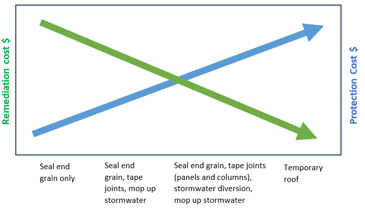
Figure 10: Cost and benefit relationship for moisture management, illustrating the escalating remediation cost as the level of proactive protection decreases. Image credit: Based on Truebeck Construction
The key message is that protection costs represent a small percentage of overall construction budget, while remediation costs escalate rapidly and unpredictably. Even minor remedial work on stained or moisture-affected exposed timber can exceed the cost of the preventive measures that would have avoided it. From an insurer's perspective, a project with a documented, comprehensive moisture management plan represents a materially lower risk than one relying on reactive measures.
Insurers increasingly expect a formal Water Management Plan that addresses both temporary and permanent water supply risks. CIREG's recommendations cover four areas.
Appoint a competent responsible person to oversee water risk management throughout the project. Phase construction to minimise potential damage to completed work. Install permanent drainage early. Label pipework and valves as work progresses so they can be identified quickly in an emergency. Route temporary water services to minimise damage potential if a leak occurs. Avoid combining service risers, excessive joints, and concealed pipework where possible. Include isolation valves, drainage points, and mitigation features in designs. Specify automatic flow monitoring and shutoff devices that can detect abnormal water flow and isolate the supply.
Use only qualified, certified plumbers. Implement a Water Work Permit system for all work on live plumbing systems. Validate installations before enclosing them behind walls or other finishes. Subject all pipework to documented pressure testing per manufacturer guidelines. Maintain a complete audit trail of components, installation, and testing.
Install flow detection and rapid shutoff capabilities on all systems. Isolate temporary water supplies when the site is unattended. Program automatic shutoff devices at mains inlets and booster pumps on each floor to cut supply outside working hours. Insulate and heat-trace external temporary pipes where cold weather is expected.
Define clear procedures in the Water Management Plan. Train an emergency response team, including out-of-hours support. Provide equipment (wet vacs, pumps, spill kits) on site for rapid deployment. Investigate and document every incident to prevent recurrence.
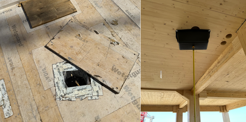
Figure 11: Floor sump installed to drain stormwater away from the building during construction. From original guide. Image credit: TDA
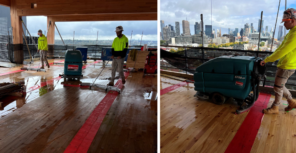
Figure 12: Dealing with stormwater on the construction site. From original guide. Image credit: ICON
Insurers may ask how moisture is monitored at each stage: manufacturer's premises, during transportation, in temporary storage, and on the construction site. The expectations are set at each point by best practice:
During manufacturing, moisture content is checked at multiple stages from log delivery through kiln drying to final quality control before dispatch. At the remanufacturer's premises, monitoring continues during machining, grading, lamination, and pressing. Before shipping, moisture levels are verified and documented.
During transportation, data loggers with moisture sensors can record conditions throughout the journey. Moisture indicator stickers provide an irreversible visual record of whether excessive moisture exposure has occurred. On arrival at site, moisture content should be checked against the manufacturer's specifications.

Figure 13: Example of on-site checks including moisture content verification on delivery. Image credit: XLam Australia
On the construction site, monitoring ranges from handheld resistance and capacitance meters for spot checks through to embedded sensors for continuous monitoring of critical elements. Be aware that handheld moisture meters measure moisture at the specific point of contact, not across the entire element. Thick timber elements exhibit a moisture gradient, with surface moisture differing from core moisture, and readings can be affected by nearby conductive materials such as steel, or by the adhesive layer aligning with the depth of the meter's pins. The only fully reliable method for determining moisture content is oven-drying a sample per AS/NZS 1080.1, but non-destructive methods are adequate for ongoing site monitoring when their limitations are understood.

Figure 14: Resistance moisture meter in use. From original guide. Image credit: TDA

Figure 15: Temporary continuous moisture monitoring system. From original guide. Image credit: SMT Research
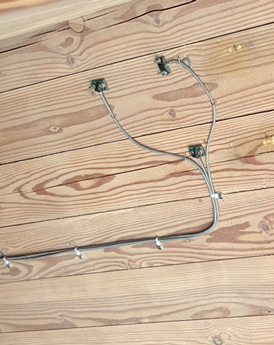
Figure 16: Temporary point moisture measuring installed in mass timber. From original guide. Image credit: TDA
For areas of high moisture risk: roofs, green roofs, balconies, consider permanent moisture detection systems for continuous monitoring post-construction, along with access panels or liftable surfaces to allow periodic inspection of concealed timber elements.
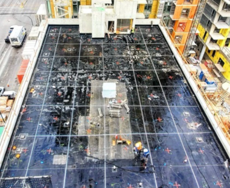
Figure 17: Permanent moisture monitoring grid for high-risk areas. From original guide. Image credit: SMT Research
The objective of moisture management is to install timber at a moisture content as close as possible to the equilibrium moisture content (EMC) it will experience in service, and to maintain that target throughout construction. For unconditioned indoor areas in Australia, the EMC is typically around 12 percent, with a seasonal swing of 4 to 8 percent depending on location. In air-conditioned or heated buildings, the average EMC is approximately 9 percent, with a range from 7 to 12 percent.
See the below reference table of expected moisture content values for wood stored in sheltered outdoor conditions across major Australian cities, drawn from CSIRO research. These values give an indication of the moisture content that well-wrapped and ventilated timber stored on site should approach.
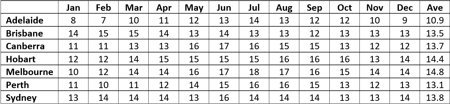
Table 1: Moisture content of wood in sheltered outdoor locations for major Australian cities, monthly values. From original guide. Source: CSIRO, 1966
For building envelope design, two references are highlighted:
WoodSolutions Guide No. 57 (condensation management) and the;
Timber Cladding Installation Standard for flashing details in Class 2 to 9 buildings.
The core principles are to keep the timber structure warm to minimise condensation, use vapour-permeable membranes, ensure proper ventilation in wall and roof assemblies, and pay particular attention to interfaces between timber and other materials.
For post-occupation moisture management, a range of moisture sources can affect occupied buildings: plumbing leaks, roofing failures, HVAC condensation, appliance malfunctions, flooding, sprinkler discharge. Construction-phase strategies, such as retaining permanent stormwater sumps, provide ongoing protection. Designing for condensation, in particular, is a long-term consideration addressed in detail by WoodSolutions Guide No. 57.
One of the most consequential questions insurers ask about mass timber is: "What happens after damage occurs?"
Can elements be repaired, or must they be replaced?
The answer directly affects claim costs, reinstatement timelines, and the overall risk profile of a building over its lifecycle. This space is one of the strongest arguments in favour of mass timber's insurability: in most scenarios, fire and water-damaged mass timber can be assessed, repaired, and returned to service using established methods.
In most mid to high-rise mass timber buildings, the structure will feature automatic sprinklers. Fires typically originate in building contents or furnishings rather than in the structural timber itself. As a fire grows, the nearest sprinkler head activates (typically within two to four minutes of ignition) discharging water that cools the fire and surrounding area, wets nearby combustibles, and prevents further spread.
In most cases, sprinklers control or extinguish the fire before the structural timber is significantly involved. Where timber is exposed and charring does begin, the char layer itself acts as an insulator. The charring rate is slow (typically 0.5 to 0.8 millimetres per minute depending on species and moisture content) and sprinkler cooling reduces it further. If sprinklers do not fully extinguish the fire, the deepening char layer increasingly insulates the unaffected wood beneath, often leading to self-extinguishment.
The result is that after a fire event, mass timber structures generally retain the bulk of their structural capacity. Any timber near the fire's origin will have some charring, scorching, or soot deposition requiring remedial work, but the extent of structural damage is typically limited.
Where non-combustible fire-resistant linings protect the timber, as is common under the NCC's fire-protected timber concession, the linings absorb the fire exposure and the timber substrate may sustain little or no damage. The Deemed-to-Satisfy solution provides defined periods of insulation (for example, 45 minutes for exterior walls, 30 minutes for interior walls in mass timber construction), maintaining the timber surface temperature below 300°C. These periods are designed to protect the timber during the most intense phase of a fire.
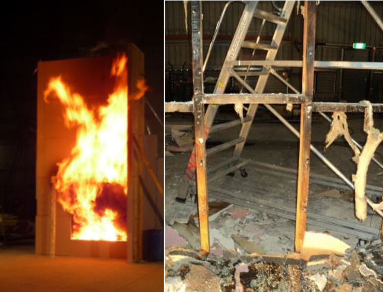
Figure 18: Timber studs protected by fire-grade plasterboard, damage after more than two hours of natural fire exposure. Image credit: Warringtonfire Australia
Understanding the post-fire structural capacity of mass timber requires understanding how wood degrades at elevated temperatures. When a timber surface is heated in a fire, three zones form in sequence: an outer char layer, a pyrolysis zone where active thermal decomposition is occurring, and a zone of elevated temperature where the wood has been heated but not yet decomposed.
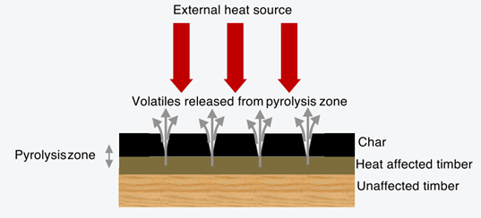
Figure 19: Pyrolysis of wood - illustrating char layer, pyrolysis zone, and zone of elevated temperature. Image credit: WoodSolutions Guide No. 18
Wood is an effective insulator. At a depth of only 8 millimetres beneath the char layer at 300°C, the temperature has already dropped to approximately 200°C.
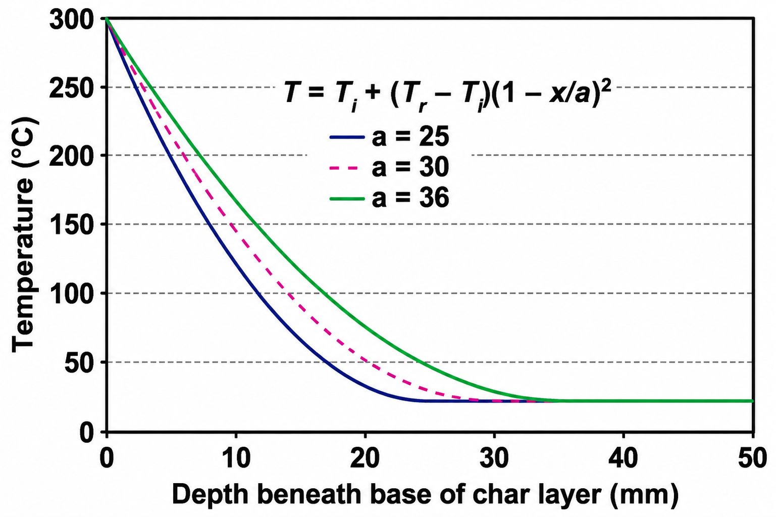
Figure 20: Temperature profile below the char layer. Image credit: Wood and Timber Condition Assessment Manual
Research by Knudson and Schniewind (1975) and Schaffer (1973, 1977) demonstrated that wood heated to these temperatures and subsequently cooled and reconditioned to 12 percent moisture content retains more than 80 percent of its original tensile and compressive strength. This is consistent with the fact that most kiln-dried timber in Australia is subjected to temperatures of 140 to 200°C during its drying process, and regains its base strength after drying.
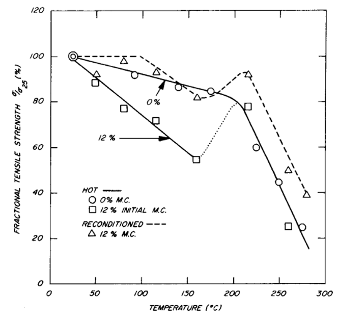
Figure 21: Percentage of tensile strength to base strength as a function of temperature, and upon reconditioning to 12% MC. Image credit: Wood and Timber Condition Assessment Manual
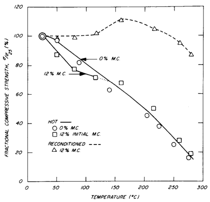
Figure 22: Percentage of compressive strength to base strength as a function of temperature, and upon reconditioning to 12% MC. Image credit: Wood and Timber Condition Assessment Manual
This means that the residual load-carrying capacity of a fire-damaged mass timber member can be estimated by determining the uncharred cross-section and reducing it by an additional allowance for the heat-affected zone, then applying standard engineering design procedures to the remaining section. The unaffected wood beyond these zones retains its original structural properties.
There is no definitive method for determining the depth of heat-affected wood. Below are five different standards and research sources, which result in different values:
It is generally recommended to follow whichever standard was used for the original fire resistance analysis of the building, rather than selecting values from different sources. This is because each standard makes different underlying assumptions. For example, the Australian standard uses a more conservative char rate than the Eurocode, which compensates by specifying a smaller heat-affected zone. Mixing assumptions across standards can produce non-conservative results.
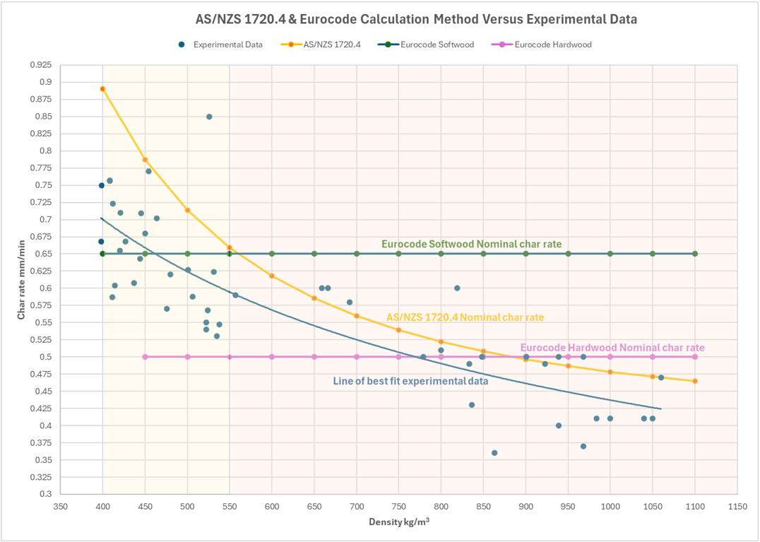
Figure 23: Comparison of AS/NZS 1720.4 and Eurocode nominal char rate equations against experimental data for various timber species and densities
Once a fire has occurred and the structure has been made safe, a condition assessment is required to determine which elements can remain in place, which can be repaired, and which must be replaced. Because mass timber elements are typically too large to remove for laboratory testing, assessment is conducted in situ using non-destructive evaluation methods. There are two primary references for this process:
Techniques include resistance drilling for density assessment, screw-withdrawal testing, hardness testing, sound and stress wave evaluation, tomography, 3D scanning, and computational modelling. The assessment extends beyond the elements directly affected by the fire: elevated temperatures causing thermal expansion or contraction may have affected other members and connections, and these should also be inspected.
Fire-damaged connections require particular attention. Metal components can conduct heat into the timber at the connection point. However, the degree of damage depends on the quality of the metal and the extent of exposed surface area. It includes an example of aluminium connectors used in a beam-to-beam connection that were exposed to more than two hours of standard fire in an AS 1530.4 furnace, with the metal temperature reaching a maximum of only 100°C.
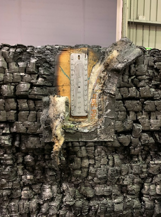
Figure 24: Aluminium connectors in a beam-to-beam connection after more than two hours of standard fire exposure. The metal temperature reached a maximum of 100°C. Image credit: TDA
The appropriate repair method depends on the fire protection strategy used in the building and the extent of damage.
Repair typically involves replacing the damaged linings rather than the timber structure beneath. The NCC fire-protected timber concession requires cavities within fire-rated elements to be filled with non-combustible insulation, and cavity barriers to be installed in adjacent cavities, both of which limit fire spread and reduce the likelihood of damage to the timber substrate. A post-fire check of cavities near the fire-affected area is necessary, either by removing linings or using thermal imaging.
The timber should retain most of its structural capacity. Damage is typically superficial: charring, smoke staining, and water effects on the visual surface. Repair can proceed using the methods described in the following section on repairing damaged timber.
A more detailed structural assessment is needed. The distinction between standard fire curves used in laboratory testing and natural fire behaviour is important here. Standard fire curves were developed in the early 20th century and are still used for regulatory compliance. They produce consistent charring over long durations (90 to 120 minutes). Natural fires are typically shorter (20 to 60 minutes in residential settings), may char at a faster rate during the growth phase, but generally result in less total char depth due to shorter exposure. The decay phase of a natural fire has a slower charring rate, and total structural loss is often less than laboratory testing would suggest.
An important structural nuance: different element types have different governing design criteria. Beams and floors are often sized by stiffness (modulus of elasticity) rather than strength, meaning they may have more cross-section than is strictly needed for safe load-carrying. This may provide a margin of safety after charring. Columns and tension members, however, are typically strength-governed and require closer examination of residual capacity.
For localised char damage, remediation involves removing charred material by sanding, scraping, or abrasive blasting, with deeper sections removed by chisel or curved blade. Once all char is removed, affected surfaces are sealed to prevent residual smoke odours from lingering, and to limit moisture ingress. For lightweight timber frame elements such as studs if charring exceeds 6 mm, replacement is generally appropriate; if less than 6 mm, the char can simply be removed.
Treated or sealed timber surfaces exposed to smoke should be cleaned to remove soot residue. Unfinished surfaces are more susceptible to soot staining and smoke odour absorption, and may require sanding and sealing. All fire residues should be removed from structural members before interior finishes are applied.
Assessment of moisture damage follows a similar logic to fire damage: identify the extent and severity, determine the cause, and assess whether repair or replacement is needed.
Visual indicators of moisture damage can include:
large cracks indicating significant moisture content changes
discoloured sections showing black rot or coloured fungal growth
stained finishes
excessive structural deflection
pervasive musty or mouldy odours
Spot checks with a moisture meter should probe various depths of the timber, particularly surfaces closest to the moisture source. Thermal imaging can help identify moisture sources, as wet timber typically appears cooler than surrounding dry material. Core samples can be taken for laboratory analysis where glue bond integrity is a concern.
Timber draws moisture along the grain, meaning that damage may have spread further than is visible from one surface. CLT panels, with their alternating grain directions, can draw water along cross-grain layers deeper into the panel than the longitudinal layers may suggest.
Some checking (longitudinal splitting) of mass timber is natural and should be anticipated. Visual stress grading standards allow checks of up to 3 mm width for hardwood and 2 mm for softwood. Excessive checking from construction-phase moisture exposure may appear once the building reaches its final equilibrium moisture content. If concerns arise, the supplier and a structural engineer should be consulted.
Including excessive checking should ideally be carried out after the timber's moisture content has stabilised. Methods include epoxy or putty filling for small cracks (noting that seasonal movement may cause cracks to open and close), routing out and gluing in timber fillets of the same species, and screw reinforcement across cracks to prevent further movement. Outcomes should be monitored and recorded for a minimum of 24 months.
Where rot has begun, requires project-specific structural assessment. All fungus-affected timber should be removed, noting that fungal hyphae can travel along timber fibres beyond the visible extent of decay. Cut surfaces should be treated with a boron-based preservative. Structural repair details will vary between projects but may include routing out and replacing lamellas, epoxy repairs with steel or timber strengthening plates, or installation of relieving structures. Fire resistance must be reinstated, and ongoing moisture monitoring (such as embedded sensors) should be considered.
Where a mass timber element has sustained localised mechanical damage (impact, gouging, or surface crushing), the affected area can be cut out and replaced with a matching timber infill. The process is as follows.
Determine whether the damage is mechanical or the result of rot. Rot-affected timber may require brush-on preservative treatment before repair, which is a separate procedure. Consider whether filling with epoxy or putty is sufficient, or whether a timber replacement is more appropriate for the location and finish requirements.
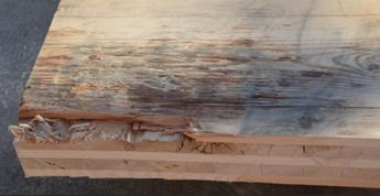
Figure 25: Mechanical damage to a CLT panel requiring repair. Image credit: CWC
Define the boundary of the area to be worked on, allowing a clean margin around the damage. Clean up the edges where required.
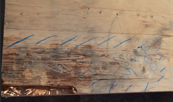
Figure 26: Defined area to be repaired. Image credit: CWC
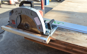
Figure 27: Cleaning up the edge of the panel. Image credit: CWC
The affected wood is removed using a saw cut to the maximum depth of the damage, with closely spaced cuts across the area. The remaining material between cuts is chiselled out to produce a flat, clean surface ready to receive the new timber piece.
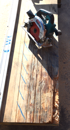
Figure 28: Cutting out the affected area using closely spaced saw cuts. Image credit: CWC
Select a timber infill piece of the same species and manufacturing process as the element being repaired. Cut it to fit the prepared area.
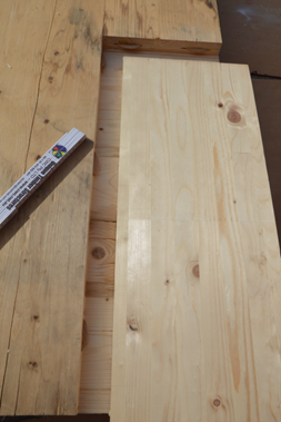
Figure 29: Infill piece of matching timber species and manufacturing process. Image credit: CWC
A mechanical fixing method is used to key the infill into the original timber, either jointer biscuits or a tongue-and-groove detail. Biscuit joints are cut into both the original timber and the infill piece.
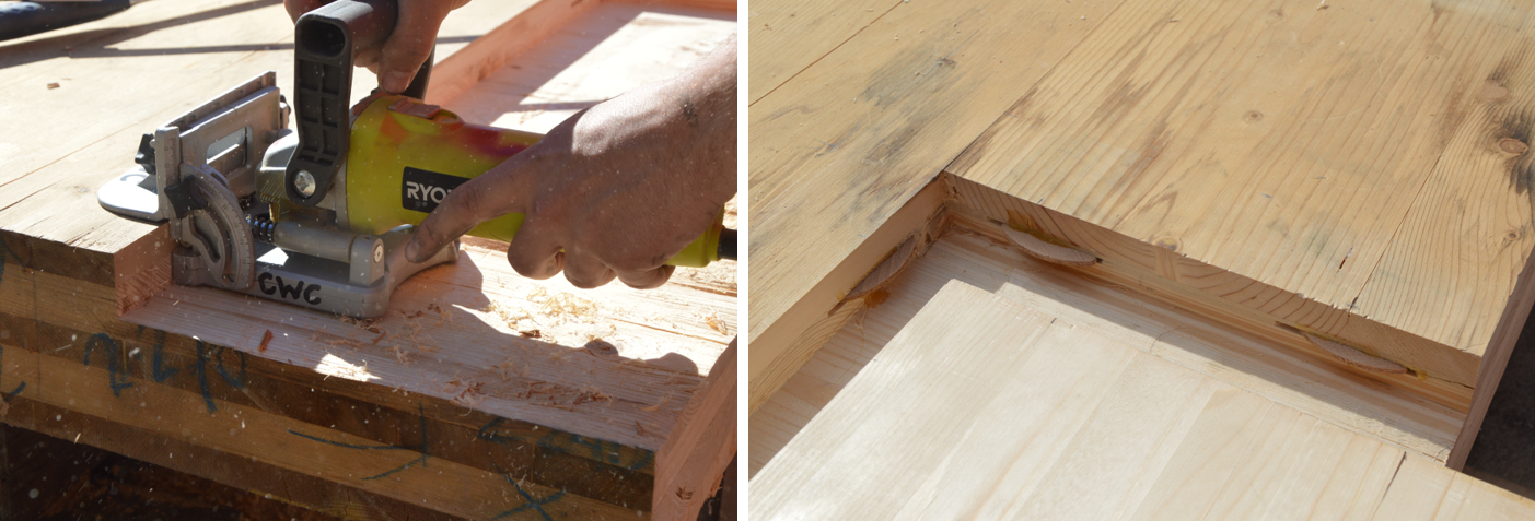
Figure 30: Biscuit joint prepared in the original timber. Image credit: CWC
Adhesive is applied. The type and product should match those used in the panel's original manufacture (typically polyurethane glue for CLT). The infill piece is set into position and pressure is applied using clamps, screw fixings, or both.
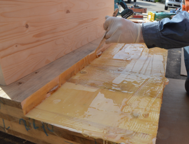
Figure 31: Polyurethane adhesive applied to the prepared area. Image credit: CWC
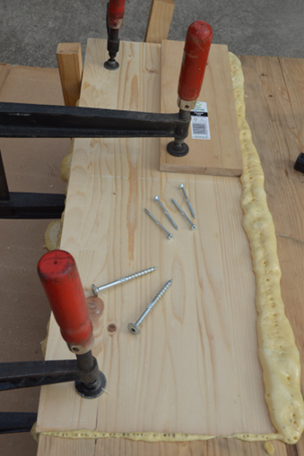
Figure 32: Clamp pressure applied to the repaired section. Image credit: CWC
Once the adhesive has cured (typically one to four hours depending on the adhesive type), excess adhesive on the joint lines is cleaned up. The repaired area is sanded and blended with the surrounding panel to produce a finished surface.
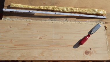
Figure 33: Excess adhesive removed after curing. Image credit: CWC
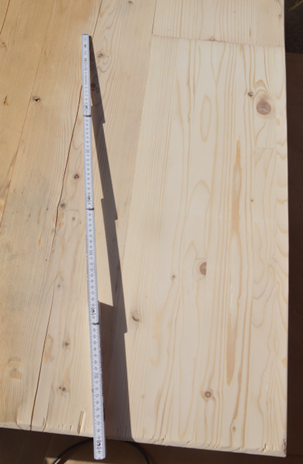
Figure 34: Completed repair blended into the base panel. Image credit: CWC
Longitudinal cracking (checking) in mass timber is natural to a degree, but where cracks exceed acceptable limits or affect the intended finish, they can be repaired using a similar cut-and-infill approach. The crack and surrounding area are assessed, and infill timber strips of matching species are prepared.
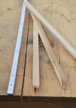
Figure 35: Crack to be repaired, with infill pieces prepared. Image credit: CWC
A slot is milled along the crack using a router or small saw to create a clean, uniform channel to receive the infill strips.
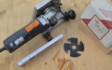
Figure 36: Small saw used to cut the slot along the crack. Image credit: CWC
The timber strips are bonded into the slot using compatible adhesive and allowed to cure under pressure.
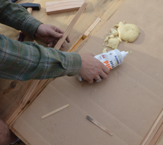
Figure 37: Timber strips bonded into the prepared slot. Image credit: CWC
Once cured, the excess adhesive is removed and the repair is sanded to blend seamlessly into the base panel.
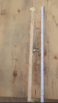
Figure 38: Repaired crack awaiting final sanding. Image credit: CWC
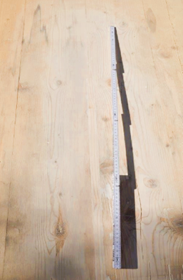
Figure 39: Completed crack repair, fully blended into the base panel. Image credit: CWC
For smaller defects where a timber infill is unnecessary, the damaged area can be filled with putty or epoxy. Epoxy generally provides a better finish quality, as it tends to blend into the base timber more effectively than putty. This method is suitable for minor surface damage, small gouges, and shallow defects where structural repair is not required.
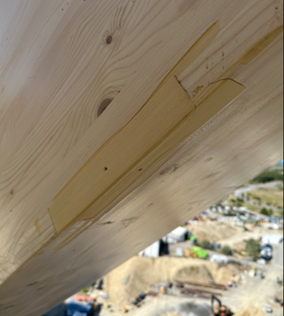
Figure 40: Putty used to repair mechanical damage to glulam.
The choice between timber infill, crack repair, and filler depends on the size and depth of the damage, whether the element is structural or decorative, and the finish expectations for the space. For exposed timber that forms part of the building's interior aesthetic, timber infill repairs provide the most seamless result. For concealed elements or areas that will receive further finishes, epoxy or putty filling may be sufficient and faster to execute. In all cases, the repair should be carried out by personnel familiar with mass timber construction, using materials compatible with the original product.
Where fire damage is the cause, all char and fire residue must be fully removed before any repair is undertaken, and affected surfaces should be sealed to prevent residual smoke odours before finishes are applied. Where moisture damage has caused rot, all fungus-affected timber must be removed, including beyond the visible extent of decay, as fungal hyphae can travel along timber fibres, and cut surfaces treated with a boron-based preservative before the structural repair detail is installed.
Mass timber surfaces can be affected by mould growth and UV discolouration during construction. Neither issue compromises structural performance, but both affect visual quality and can raise concern among project stakeholders and insurers if not anticipated and managed.
When mass timber is described as sunburnt, this refers to colour change caused by exposure to ultraviolet light. UV rays trigger photochemical oxidation of lignin and extractives in the wood, producing yellow-brown decay products. In light-coloured species such as fir, pine, or larch, the timber yellows; in darker species, it shifts toward pale brown. The first stage of yellowing can occur within days of exposure, depending on species and climate conditions.
If anything covers the timber during the oxidation period (props, temporary bracing, protective wrapping) the covered area cannot react and will appear lighter than the surrounding timber once uncovered. The exposed timber will eventually catch up in colour, but the edges where covering sat often remain visible as a colour boundary. UV-driven colour change is a finite process, largely completed within the first three to six months, though some further change continues up to a year.
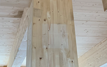
Figure 41: Sunburn mark on mass timber from construction props - showing colour differential where timber was covered. Image credit: TDA
The most effective preventive measure is to cover exposed elements, particularly columns and beams on the exterior wall line, with a vapour-permeable membrane, a temporary panel product, or both. The panel product also protects against accidental mechanical damage. Prefinished timber with UV-resistant coatings will resist colour change in most cases, though performance depends on the level of UV exposure.
Where sunburn has occurred, repair involves sanding the entire face of the affected element back to bare timber. The oxidation is only a surface reaction, leaving the wood immediately below unaffected. Alternatively, a cleaning agent can be applied to strip the oxidised surface layer. Spot repair of individual affected areas is not recommended, as the result tends to appear patchy. The full face of the component should be sanded, repaired, and recoated as required.
Mould is a fungus that feeds on starches and sugars present on the timber surface. It appears as sooty black growth and can spread rapidly in warm, humid conditions. Mould growth is superficial. It does not affect the structural performance or durability of timber elements, but it is unsightly and, if left unmanaged, can raise concerns about building quality and indoor air quality.
Mould spores are always present in outdoor and indoor environments, distributed by wind, insects, water, animals, and human activity. Mould will colonise a wide range of construction materials, not just timber: plasterboard, fibreglass insulation with surface coatings, and any material containing organic content can support growth when wet. Exposed soil within a building, such as a dirt subfloor space, is another common growth site.
Three conditions must be present for mould to grow on timber:
Moisture content above 19 percent sustained for a week or more,
Temperature between approximately 4°C and 30°C (with optimal growth at 25–30°C),
Presence of spores - which is effectively universal and uncontrollable.
Of these three, moisture is the only one that can be practically controlled on a construction site.
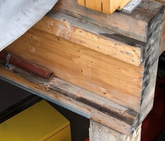
Figure 42: Mould growth on a timber beam. From original guide. Image credit: TDA
Water is often drawn into timber through exposed end grain, making end-grain sealing a critical preventive measure. All end grains of any timber element should be sealed with a coating or vapour-permeable membrane before exposure to site conditions.
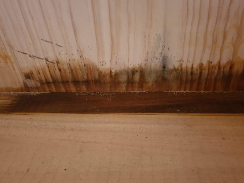
Figure 43: Water uptake through exposed end grain of timber. From original guide. Image credit: Arboralis
Where mould has occurred, proprietary biocide products can kill the growth and restore the timber's appearance. Bleach is not recommended as it cannot penetrate below porous surfaces and mould will return as roots remain active beneath the treated surface. High-pressure water cleaners are also not recommended, as they dislodge surface fibres, destroying the milled finish, and increase the timber's moisture content, potentially promoting further mould growth.
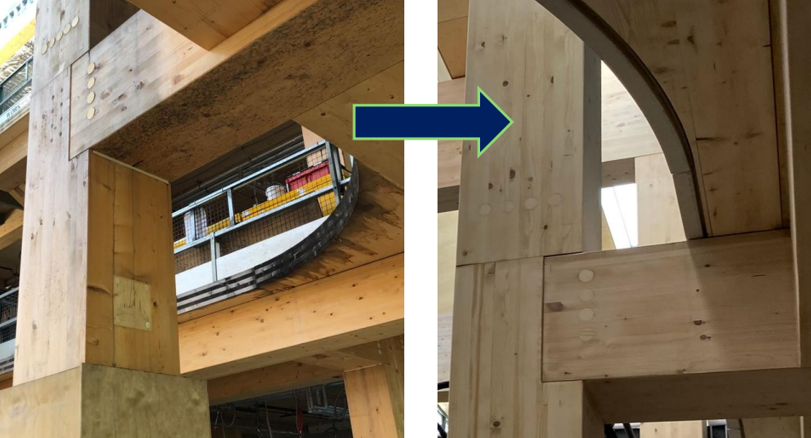
Figure 44: Before and after - mould-affected glulam remediated with proprietary biocide cleaner. Image credit: Intergrain
Insurers frequently ask whether the adhesives used in mass timber products have been tested for fire resistance. This is a reasonable question, since the structural integrity of engineered products such as glulam, CLT, and LVL depends on the bond between laminations remaining effective under load and, in a fire, for the required duration.
There are two pathways by which mass timber products can be assigned a fire resistance level under the NCC, and the adhesive question is addressed differently in each.
The Australian standard for fire resistance of timber elements limits the structural adhesive to phenol, resorcinol, phenol-resorcinol, or polyphenolic formulations, the adhesives commonly recognised as the dark bond line between laminations. These adhesives are thermosetting (they harden irreversibly) and resistant to heat, with a history of use in engineered wood products spanning over 100 years and demonstrated performance in fire conditions.
This standard has not yet been updated to reflect modern adhesives such as polyurethane and melamine, which have also demonstrated adequate fire performance. Products manufactured with these newer adhesives cannot use the AS/NZS 1720.4 calculation method and must instead demonstrate fire resistance through prototype testing.
AS 1530.4 provides a standardised fire resistance test in which a prototype building element is exposed to a standard fire curve. The period during which the element resists structural failure, maintains insulation, and preserves integrity determines its fire resistance level, rounded down to the nearest 30-minute interval. Because the adhesive is part of the tested assembly, any fire resistance level derived from this method inherently demonstrates that the adhesive performed adequately for the tested duration.
The NCC allows accredited testing laboratories to interpret test results for minor variations such as changes in product length or thickness, through assessment reports. Products using modern adhesives not recognised in AS/NZS 1720.4, including most CLT and some glulam products, typically rely on this prototype testing pathway.
Separately from fire performance, all mass timber products meeting Australian manufacturing standards must use adhesives that comply with AS/NZS 4364 (Timber - Bond performance of structural adhesives), which classifies adhesive suitability for defined environmental conditions. If a mass timber product claims compliance with an Australian product standard, the structural assessment of the adhesive has already been satisfied through that compliance pathway. Where a product does not meet an Australian standard, or no standard exists for that product type, the manufacturer must provide independent evidence of adhesive suitability, typically documented in their Product Technical Statement.
Insurers occasionally ask whether mass timber produces unusual or elevated toxic emissions when involved in a fire. The combustion products generated by engineered mass timber do not differ significantly in chemical composition or toxicological profile from conventional wood-based materials that have been permitted as wall, floor, and ceiling linings under the NCC for decades. Fire services' existing operating procedures and tactical approaches do not require modification when responding to incidents involving mass timber structures.
It is worth noting that modern building contents, particularly synthetic polymers in furnishings, finishes, and fittings, often present more significant toxicological hazards upon combustion than the timber structure itself.
Fixing building services to mass timber elements does not significantly affect the structural or fire performance of the timber, provided fixings are designed in accordance with AS 1720.1 and notches and holes remain within the limits set out in AS 1684.
For fire performance, small fasteners do not materially reduce the fire resistance of mass timber. Where fire-resistant linings are fixed to mass timber, the fastener arrangement is part of the tested fire-resistant assembly, so the fire resistance determination already accounts for their presence. The primary concern is whether fasteners retain their holding capacity after a fire. To ensure this, embedment depth should extend beyond the expected char and zero-strength zone. Typically, this minimum embedment is seven to ten times the fastener's diameter
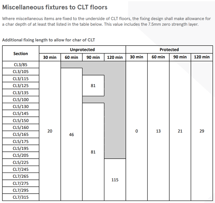
Figure 45: Char depth and zero-strength zone for XLam CLT at various fire resistance levels, for both encapsulated and exposed elements - showing required fastener embedment depth. Image credit: XLam
Fire compartments
Insurers may ask whether escape pathways (protected stairwells, internal corridors) are fabricated from or lined with mass timber, and to what extent. This is not a technical concern so much as a mapping exercise: clearly documenting where mass timber is used in fire compartments, escape routes, atria, and openings between storeys allows insurers to assess the fire scenario for each compartment type. This information should be readily available from the fire engineering documentation prepared for NCC compliance.