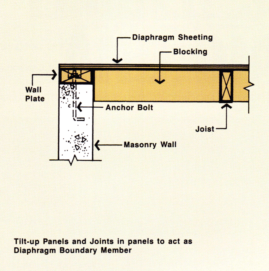
Framed timber buildings, of post and beam or stud and joist construction, resist lateral loads (wind, earthquake or impact) by using rigid frames (portals), braced frames (trusses and cross-bracing) or structural sheathing elements (diaphragms).
Diaphragms are an efficient structural solution to resist lateral forces. The sheeting materials that are generally used as lining or cladding can usually be upgraded to resist shear loads, easily and economically. The framing then performs dual functions, resisting both horizontal and vertical loads.
In cases where diaphragms comprise structural sheathing, additional design efficiencies can be incorporated to resist loads normal to walls, floor and roofs using the composite stressed skin action developed between the sheathing and the timber frame.
The advantages of timber shear walls and diaphragms include:
- architectural design freedom (curves, cantilevers, clear spans)
- lightweight construction
- high impact load resistance
- resilience (no brittle cracks)
- fast conventional construction
In this section you'll find information about the design and construction details of timber framed diaphragms (both horizontal and vertical) used in domestic, low rise commercial and industrial buildings.
Framing design for dead loads, or dead and live loads acting normal to the framing are covered in AS 1720.1 Timber Structures and AS 1684 Residential timber-framed construction. To develop efficient diaphragm action, some adjustments, particularly connection details, are usually required.
Information about diaphragm materials and systems is included, however the majority of the design and construction details provided herein are for structural plywood diaphragms for which documented design information is available.
Criteria Level: 1
In situations where appearance or architectural requirements dictate, timber or plywood shear walls and diaphragms provide both a decorative and structural solution, using either diagonal boards (sawn textured or smooth), or plain or grooved plywood, either internally or externally.
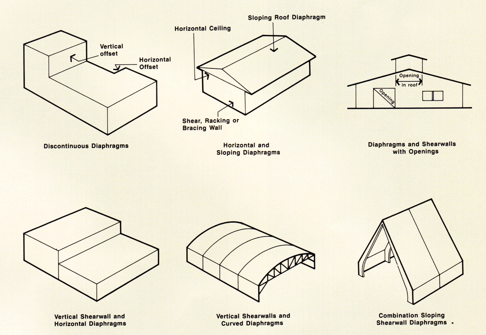
Typical applications
Criteria Level: 2
Shear walls and diaphragms must be:
- strong enough to resist the applied forces
- stiff enough not to deflect excessively under normal serviceability conditions
- stable, i.e. show no obvious signs of buckling at design load levels.
To ensure each of the above requirements are satisfied, design consideration should be given to:
- sheathing thickness
- nailing pattern
- chord and stud design
- system deflections
- support connection requirements
Criteria Level: 3.01
To function effectively, a shearwall may have to resist:
- bending due to normal and suction wind forces
- uplift forces due to the wind passing over the roof
- racking forces from wind loads transferred to the ceiling or roof and then to the shear walls
However, it is usually the unit shear which controls shearwall sheathing thickness and published manufacturers' literature, based on test results, provides design details.
Criteria Level: 3.02
Nailing pattern (nailing density), together with nail diameter and length determine the sheer resistance of a panel. Manufacturers' literature provides details of appropriate nail spacings versus shear capacity.
Criteria Level: 3.03
In standard dwelling construction, these members are the studs and plates. Framing sizes are available from AS 1684 Residential timber-framed construction.
When designing industrial and commercial buildings, the framing in shear walls which may be more than a sheet length in height, should be checked for strength. Data available for shear walls used in dwellings may be used provided:
- the same framing member stress grade and joint strength group timber is used for the wall framing (or it may be greater to accommodate lateral loads)
- the same sheathing grade and thickness is used
- the nailing pattern and nail diameter and length is maintained
- studs and plate sizes are checked by design to ensure they can sustain the applied loads due to dead, live, wind and seismic loading
Criteria Level: 3.04
It is possible, by testing isolated shear walls, to develop relationships to evaluate eaves deflections, however, test relationships bear little resemblance to actual deflections of walls in structures because:
- in practice loads are applied through discrete points via joists, rafters and ceiling or roof diaphragms
- additional transverse walls and ceilings are interconnected so reducing the overturning effect
- shear walls may be interconnected to a relatively flexible ceiling or roof diaphragm which, when it deflects, can transfer lateral loads into walls at right angles to the shear walls.
Criteria Level: 4
The response of diaphragms is similar to shear walls and requires consideration of the following:
Criteria Level: 4.01
As was the case with shear walls, diaphragms usually have to perform more than one function. For diaphragms, thickness is normally controlled by its ability to resist dead, live and wind loads normal to the surface of the sheathing.
Minimum thicknesses of diaphragms in sheathing for floors, ceilings and roofs can be determined by reference to manufacturers specifications.
The shear resistance of diaphragms (strength and stiffness) is therefore usually controlled by nail sizes and spacings.
In some instances, where thin ceiling or roof diaphragms are used, shear strength may be controlled by thickness.
Criteria Level: 4.02
Diaphragms vary in load carrying capacity depending on whether or not they are 'blocked'.
Blocking consists of nogging (framed between joists or other primary framing) to which the sheathing is connected. This provides additional shear transfer and hence unblocked diaphragms are usually less stiff than blocked diaphragms.
For shear load data, please refer to AS 1720.1 Timber structures.
Criteria Level: 5
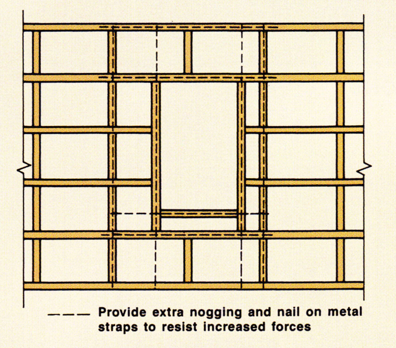
It is often necessary to provide openings in both shear walls and diaphragms. When this occurs, a redistribution of forces around the opening is necessary in order for the applied loads to be satisfactorily resisted. If openings are small compared to the overall dimensions of the shear wall or diaphragm, then no real problem is created. However, if the opening is large then considerable computations effort and component modification may be required.
Criteria Level: 5.01
Openings in shear walls are provided mainly for purposes of access (doors) and light and ventilation (windows).
It is usual to assume each panel around the opening works independently even though they are connected to each other through the lintel. For houses, it has been found that the top plate is sufficient to provide the necessary continuity for openings up to about 2.4m.
Manufacturers' literature is available, providing allowable racking loads for plywood, particleboard, diagonal timber boards and hardboard used to brace dwellings. The racking loads are usually based on test results in which panel deflections are limited to the panel height/300 or 8mm.
A design approach for dealing with large openings in shear walls has been developed using a simple equilibrium analysis.
Having an opening in a wall requires some analysis to redistribute the build-up of shear forces that occur around the discontinuity. Computer programs are available for the analysis of diaphragms and trusses but in many cases such detailed analysis is not warranted.
Criteria Level: 5.02
Openings may be located in diaphragms for purposes such as stairwells and skylights. If the opening is small in comparison to the dimensions of the diaphragm, it can be assumed it will have little effect on the redistribution of shearing forces around the hole.
Where the opening is large, it may be necessary for the designer to assess the redistribution of shear forces.
Criteria Level: 6.01
The table and figure below provide a summary of sheathing material types which can be used in shear wall and diaphragm construction.
|
MATERIAL |
ORIENTATION |
REMARKS |
APPLICATIONS |
|
Timber Boarding 12 mm - 19 mm thick |
Horizontal or Vertical
|
Requires minimum of 150 mm wide boards to develop any reasonable diaphragm action. Limited value as shear walls or diaphragms unless incorporating other braces. |
|
|
Diagonal
|
100 mm wide boards suitable. Usually requires two nails to each end of board. |
As above |
|
|
Structural Plywood 3 mm - 25 mm thick |
Depends upon application
|
Structurally very efficient. Available as either Structural (D-D Grade) or Structural and Decorative (A-D or C-D Grade). Grooved and plain sheets, sawn or smooth faces available. Resistant to moisture and wetting. Close edge nailing possible.
|
|
|
Particleboard 6 mm - 25 mm thick
|
Depends upon application
|
As for structural plywood except it should be used in interior situations only.
|
|
|
Hardboard
|
Depends upon application
|
Not suitable as flooring diaphragm unless used in conjunction with another flooring product.
|
|
|
Orientated Strand Board
|
Depends upon application
|
As for structural plywood except it should be used in interior situations only.
|
|
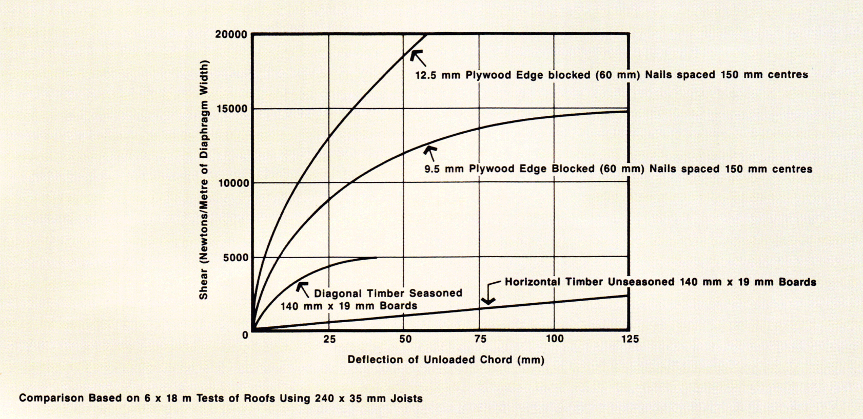
Relative performance of plywood and timber diaphragms
Criteria Level: 6.02
Structural framing to support sheathing may be of sawn timber, glued laminated timber or laminated veneer lumber.
Structural timber and timber products should comply with the relevant Australian Standards and industry quality assurance programs.
Criteria Level: 1
A diaphragm is a thin, structural element, that is flat or curved and generally rectangular. Suitably constructed wall, floor, ceiling or roof framing will, when used with structural sheathing and appropriately designed connections, act as a structural diaphragm, Vertical diaphragms, such as those occurring in walls, are usually referred to as shear walls while horizontal (or inclined) diaphragms (those occurring in floors, ceilings and roofs) are referred to as diaphragms.
Criteria Level: 1.01
Shear walls comprise timber framing sheathed with thin structural sheet or an alternative timber product, usually between 3mm and 25mm thick. The sheathing is generally stapled, nailed or glued to the frame.
When specifying the size of timber framing for the shear wall, remember that the wall may also function in bending, due to the combined suction and normal action of the wind on the sheathing surface. In some cases, the wall may also perform a tie-down function, resisting wind uplift from the roof.
Walls that resist bending, uplift and racking are described as bracing, shear or racking walls, with no reference being made to their multi-functional structural performance in a building. Due to the nature of the wall component, it is usually mounted vertically, connected through the bottom plate to a floor. Interconnection is also through adjacent and transverse walls as well as to the ceiling or roof structure. Loads are applied to the top plate of the shear wall through ceiling joists and rafters, as seen in the figure below.
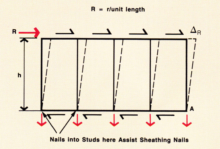
Sheathed wall racked through an eaves deflection of R
Please note that this construction technique involves fixing the sheathing to the timber framing and only connecting the bottom plate to the floor at discrete points. This prevents the development of true cantilever beam action and application of the usual bending formula for determining timber sheathing stresses.
Criteria Level: 1.02
Diaphragms are constructed in a similar manner to shearwalls, however they are generally oriented in a horizontal plane as floors or ceilings. In some cases diaphragm action can also be developed in sloping or curved roof systems. In shear walls, sheathing is usually nailed to the timber framing whereas in some floor and roof diaphragms, the sheathing may be glued using an elastomeric adhesive with nailing adding a clamping force. This type of construction has been developed to transfer live loads due to wind and occupancy. Where the sheathing is glued to the framing, the floor and roof components would be much stiffer against in-plane as well as normal loads. This is known as stressed skin action and shown in the figure below.
Forces resisted by diaphragms, which in this instance are in effect deep beams, usually result from wind loads developed on walls normal to the wind direction being transferred to the ceiling and or floor.
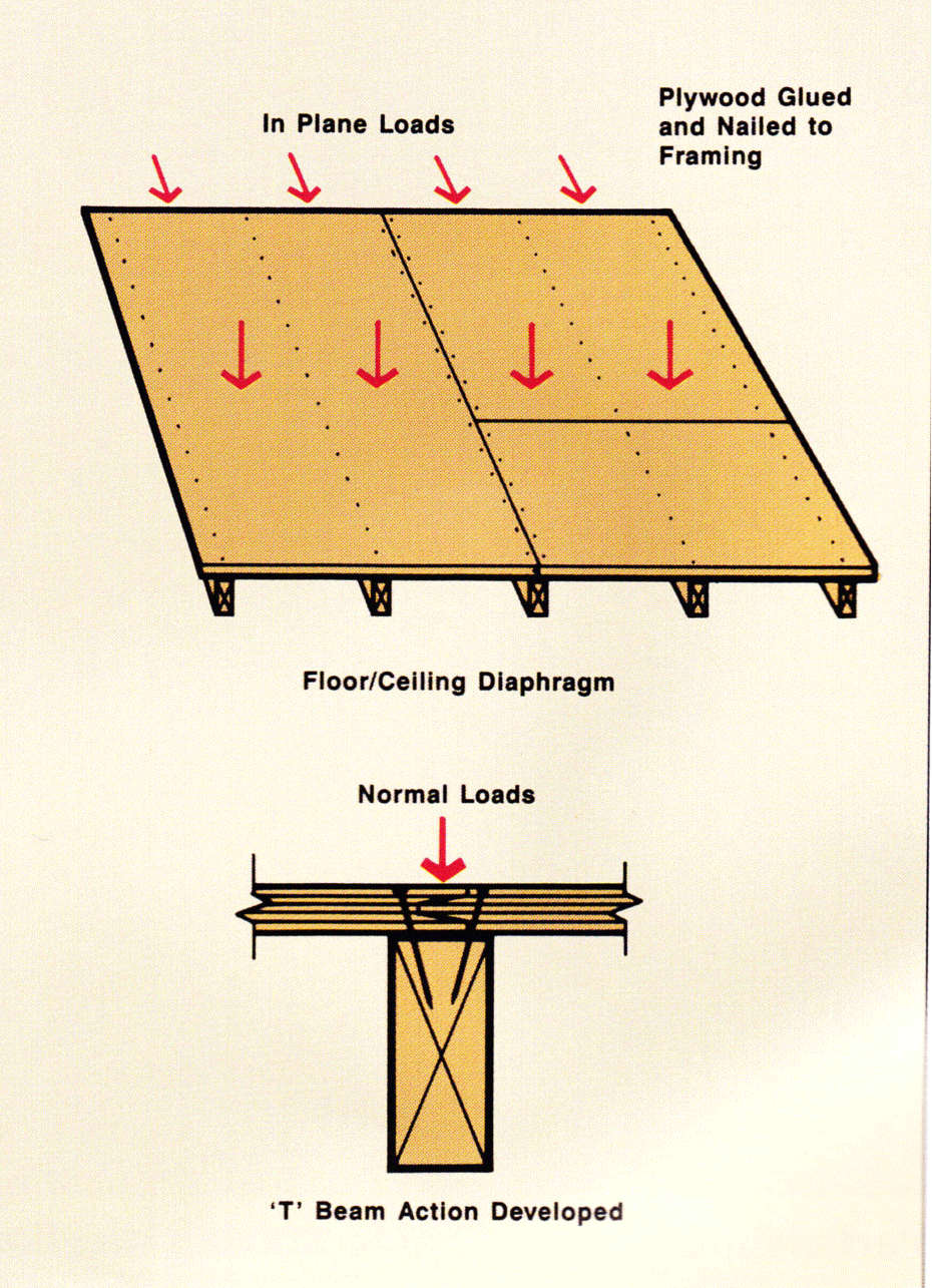
Stressed skin action
Criteria Level: 2
The following checklist covers some items which should be included in specifications or indicated on drawings.
Frame materials
- product type grade/quality
- size, spacing etc.
- frame joints
- handling and storage
Sheathing materials
- product type
- size/thickness
- grade/quality
Fixings
- fastener type/size/spacing
- edge distances
- temporary and permanent protection
Criteria Level: 1
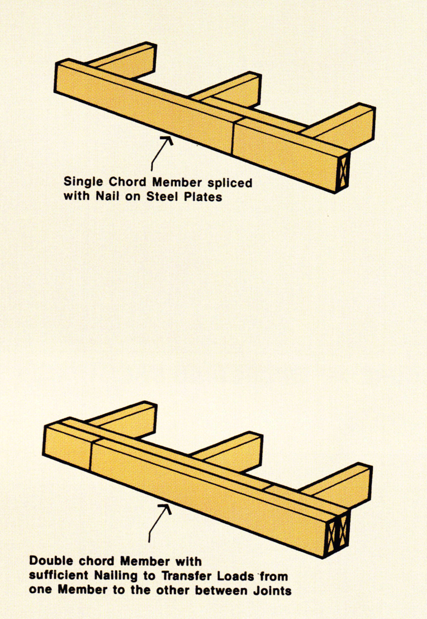
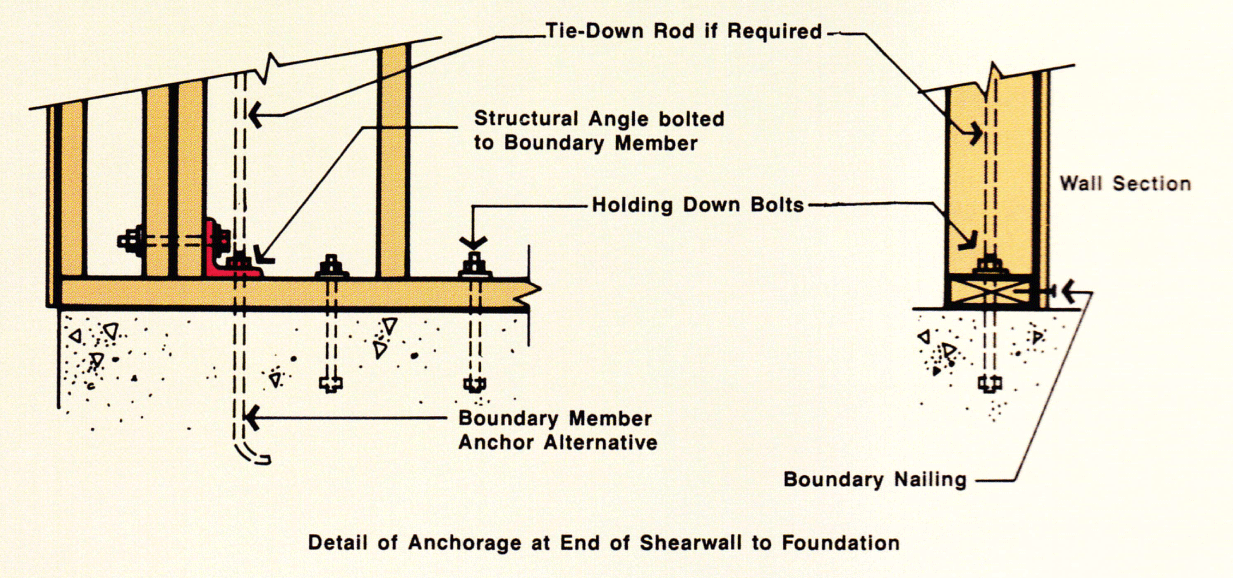
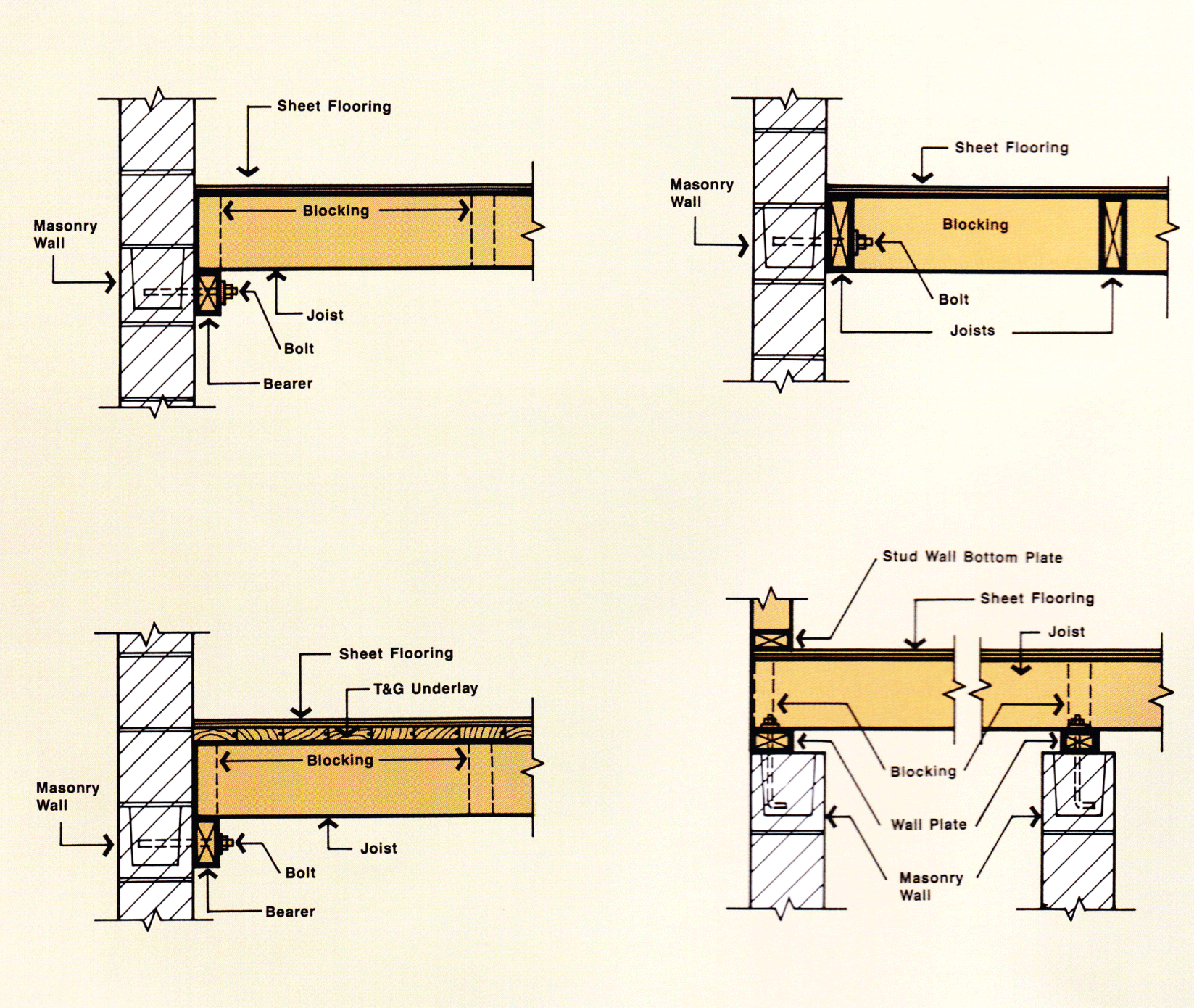
The following figures illustrate typical details for the construction of timber shear walls and diaphragms. Particular attention must be given to:
- framing connections around openings
- joining framing members
- fixing shear walls and diaphragms to floors, walls and roofs
