CLT Design, Detailing, and Construction

CLT buildings are designed differently from conventional steel, concrete, or timber frame structures. The material's large-format panels, plate-like structural behaviour, and off-site fabrication create a design workflow where coordination, connection detailing, and services integration must be resolved before fabrication - not adapted on site.

This is not a limitation. It is a design methodology that rewards early resolution, produces high-quality outcomes, and accelerates construction. The projects that run most smoothly are those where the design team, manufacturer, and builder engage collaboratively from concept stage.

This article covers structural design principles, connection types, joint detailing, sealing, cross-material interfaces, services integration, tolerance management, and construction sequencing. It assumes familiarity with CLT as a product - for material properties, adhesive systems, and manufacturing, see CLT Material Properties and Manufacture.

CLT design, detailing, and construction form an integrated process where decisions at each stage directly affect the others. Panel layout influences connection design. Connection design influences acoustic and fire performance. Services coordination influences panel fabrication. Construction sequencing influences moisture management.

The connection palette need not be complex - many successful CLT buildings have been built with self-tapping screws, angle brackets, and hold-downs applied consistently and well detailed. What matters is that connections are designed for the actual load paths, sealed for acoustic, fire, and moisture integrity, and coordinated with the panel layout and erection sequence from developed design onward.

The projects that deliver the best outcomes are those where the CLT manufacturer, structural engineer, services consultants, fire engineer, and acoustic consultant work collaboratively before fabrication begins. Model as much as required, measure twice, lift once.

Return to the CLT Guide for an overview of CLT's role in building design and links to all sub-pages.

Key Takeaways

  • CLT design is a collaborative, front-loaded process. Panel layout, connection detailing, service routing, and compliance strategies must be coordinated and resolved before fabrication begins. Changes after CNC programming are costly.
  • CLT panels act as structural plates - carrying loads in both directions, functioning as floor diaphragms, and serving as shear walls. Structural design should take advantage of this plate behaviour.
  • Connections govern system performance. Individual CLT panels are strong and stiff; the building's overall structural behaviour, acoustic isolation, and fire integrity are determined by how panels are connected to each other, to supporting elements, and to the foundations.
  • The choice of panel-to-panel joint profile (cover-board spline, half-lap, butt joint) affects structural capacity, fabrication complexity, acoustic and fire performance, and on-site fit. Select joint types early and detail them for the loads, tolerances, and sealing requirements of each location.
  • Every joint is a potential weak point for sound, smoke, fire, and moisture. Sealing - through profiling, sealants, gaskets, or tapes - must bring panel joints to the same level of integrity as the solid panel field.
  • Services must be coordinated with the panel layout from early design. CLT panels are solid - services cannot be run through the panel the way they can through a stud cavity. Routing strategies include CNC-routed channels, suspended ceilings, raised floors, dedicated service walls, and surface-mounted systems.
  • Tolerance management is critical at interfaces between CLT and other materials. CLT is manufactured to ±2 mm, but in-situ concrete may be ±10-15 mm. Shimming, adjustable connections, and survey protocols should be specified.
  • Construction sequencing should minimise the open-structure period. Just-in-time delivery, rapid enclosure, and phased installation reduce weather exposure and simplify moisture management.

Publications

1. Design Coordination

Front-Loaded Design

CLT buildings require a higher proportion of design resolution before construction begins than most conventional structural systems. Because panels are CNC-fabricated to order, all major decisions must be locked in before shop drawings are finalised: panel layout and orientation (span direction, joint locations, support positions), connection types and locations, service penetrations, routing channels, and chase locations, fire and acoustic treatment zones, lifting point positions and erection sequence, and interface details with other structural materials.

This front-loading is CLT's greatest design advantage and its most common source of difficulty. When design coordination is done well, construction proceeds rapidly with minimal rework. When it is incomplete, late-stage changes require panel re-fabrication, programme delays, and cost overruns.

Design Team Integration

The CLT manufacturer should be engaged as early as practical - ideally during developed design - to advise on feasible panel dimensions and layup options, CNC machining capabilities and limits, transport constraints (length, width, weight, road clearances), available structural, acoustic, and fire test data, and erection methodology and crane requirements.

This is not a procurement step - it is a design step. The manufacturer's input affects panel layout, connection design, and construction methodology, all of which feed back into the structural, architectural, and services design.

Panel Layout

The arrangement of individual CLT elements within each floor, wall, and roof plane is one of the earliest design decisions and one of the most consequential. It determines span direction and structural efficiency, joint locations (which affect acoustic, fire, and weatherproofing detailing), crane lifts and erection sequence, and the relationship between panel edges and architectural elements (walls, openings, stairs, services risers).

Panel layout should respond to the structural grid but also anticipate acoustic separation requirements (joints between dwellings require particular attention), fire compartment boundaries, services distribution strategy, and construction access and crane reach.


Figure 1: Panel layout example. Source: Stora Enso

Plate Behaviour

CLT panels act as structural plates rather than beams. They carry loads across their full surface and can span in both principal directions, though structural design often simplifies to one-way spanning for floor panels. The primary spanning direction is aligned with the major axis (the direction of the outermost lamellae).

Structural design takes advantage of CLT's plate behaviour in three ways: as floor and roof diaphragms (transferring lateral loads in-plane to shear walls and cores), as loadbearing walls (carrying vertical loads and acting as shear walls for lateral resistance), and as spanning elements (carrying out-of-plane loads as floors and roofs).

Design Standards

In Australia, CLT structural design is typically carried out in accordance with AS 1720.1, using manufacturer-supplied characteristic values. Some designers also reference Eurocode 5 (EN 1995-1-1), particularly for imported CLT products with European test data. AS 1720.1 does not yet specifically address CLT as a distinct product - it was written primarily for sawn timber and glulam, so engineers typically treat CLT as an orthogonal anisotropic plate and apply the bolt/screw equations with modifications for multiple layers. 

Upcoming design guidance and building codes are expected to incorporate CLT-specific factors. In the interim, many designs rely on manufacturer's data or European standards for certain checks.

Design properties are product-specific. Designers should use the manufacturer's published data - not generic CLT properties - because species, adhesive, lamella dimensions, and layup all affect performance.

Key Design Checks

The principal structural checks for CLT include:

  • Bending capacity - governed by the strength of the major-axis layers and the panel's effective section properties
  • Shear capacity - including rolling shear - a distinctive CLT failure mode where shear failure occurs within the transverse layers, governing design for short spans or heavy point loads)
  • Deflection - CLT floors can be stiffness-governed, particularly for longer spans where deflection limits may control before strength limits
  • Vibration - CLT floors are lighter than concrete and require vibration assessment for foot traffic - particularly in residential and commercial applications; where vibration performance is critical, additional stiffness may be required through increased panel thickness, reduced span, hybrid topping layers, or supplementary beams.
  • In-plane shear - for diaphragm and shear wall action - CLT's high in-plane shear capacity makes it effective for lateral load transfer
  • Bearing - at supports, CLT's cross-grain layers can be susceptible to localised crushing - bearing stiffeners or hardwood plugs can be inserted to locally reinforce the compression zone where heavy point loads bear on CLT

Lateral Stability

CLT's inherent stiffness and shear wall capacity make it well suited to lateral load resistance. Floor diaphragms transfer wind and seismic loads to shear walls or cores, and the connections between panels govern load path continuity.
In taller buildings, CLT shear walls may be supplemented by concrete cores, steel bracing, or post-tensioned rocking walls. These hybrid configurations expand the height range of CLT buildings and provide options for managing overturning, drift, and foundation loads. In seismic designs, ductile steel connectors that yield under extreme loads are preferred over rigid connections, this protects the CLT panels from splitting and provides energy dissipation.
 

Connections are the most critical aspect of CLT structural design. Individual panels are strong and stiff; the building's overall structural behaviour, robustness, and constructability are determined by how panels are connected to each other, to supporting elements, and to the foundations. Every connection must transfer the required combination of vertical loads (gravity), in-plane shear (diaphragm and shear wall action), out-of-plane loads (wind, seismic), and uplift and overturning forces. A single connection may serve multiple functions, and the interaction between load paths is a primary design consideration.

Self-Tapping Screws

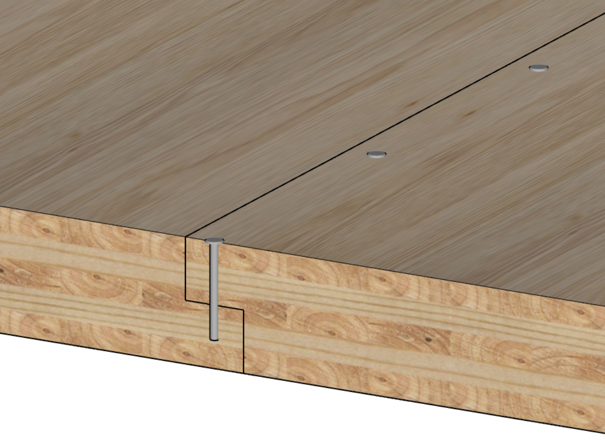
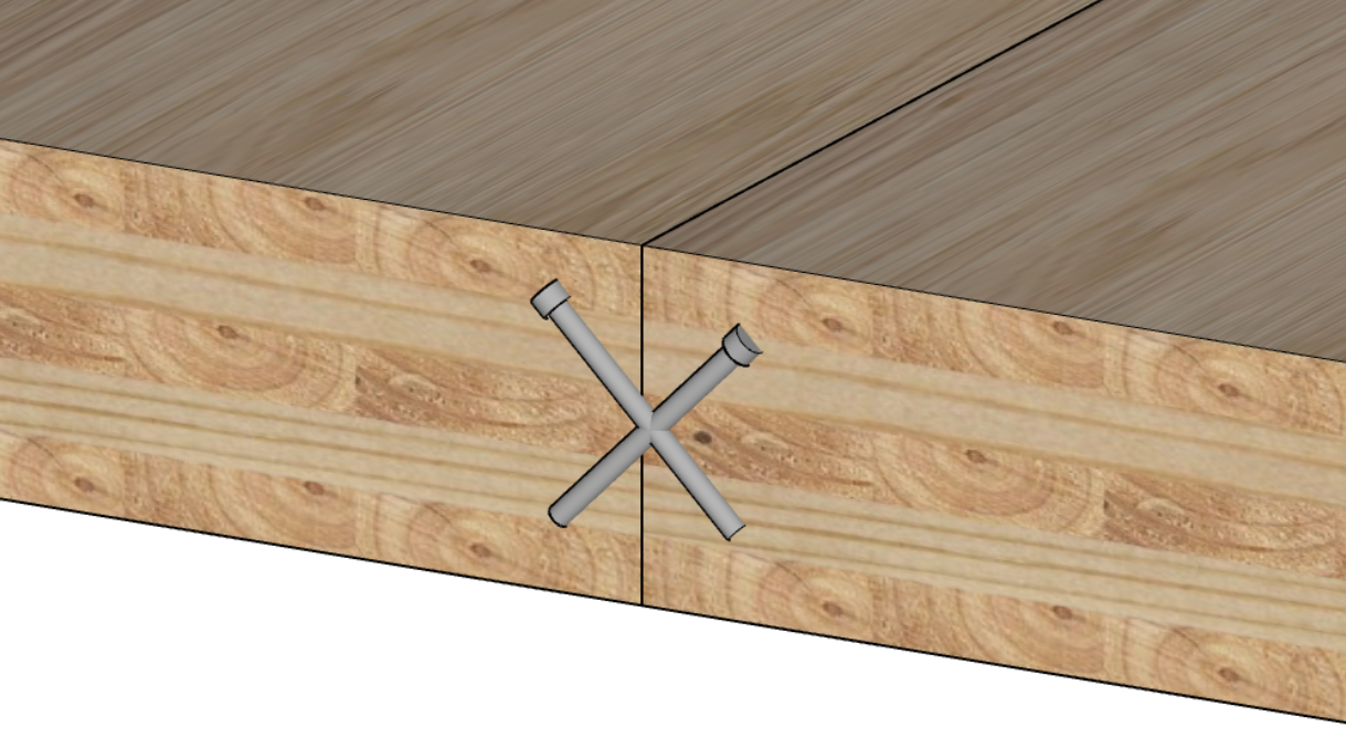
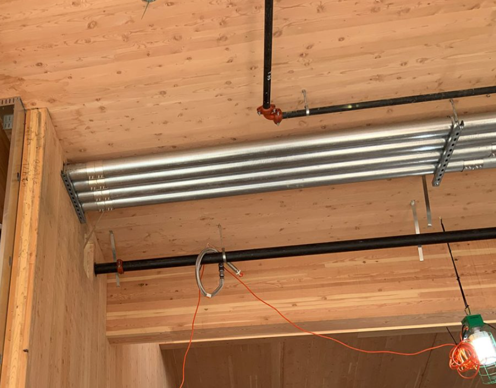
Self-tapping screws (STS) are the primary fastener in CLT construction. These engineered screws - typically carbon steel with specialised threads and hardened tips - can be driven into CLT without pre-drilling, in diameters of 8-14 mm and lengths up to 400-600 mm or more. They are used for panel-to-panel splices, angle-driven hold-downs, beam-to-panel connections, and reinforcement around openings and notches.

Self-tapping screws offer high pull-out strength and can take combined lateral and axial loads, allowing them to resist uplift while transferring shear. Their versatility means many connections can be detailed with screws alone at specific angles and spacings, avoiding the need for bulky steel plates.

When designing with screws in CLT, the layered structure must be considered. If screws are loaded in withdrawal through transverse (cross) layers or unbonded edges between lamellae, design values are adjusted accordingly. Embedment and withdrawal capacities should be verified from the manufacturer's technical literature or tested values. Engineers often reference European yield models or manufacturer-supplied data in addition to the AS 1720.1 fastener provisions.

A practical note: fully threaded screws can act as clamps, restraining the natural shrinkage and swelling of timber across the panel. While beneficial for some connections, overuse of fully threaded screws in directions that restrain moisture movement can induce splitting. The principle is to work with the dimensional behaviour of the timber, not against it.

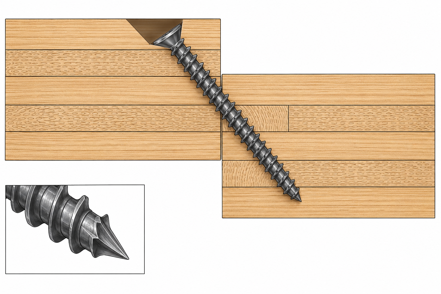
Figure 2: Self-tapping screw. When designing angled screws, be mindful of edge distances and grain directions.

Steel Plates and Brackets

Steel connectors complement screws and provide higher-capacity or more specialised load transfer.
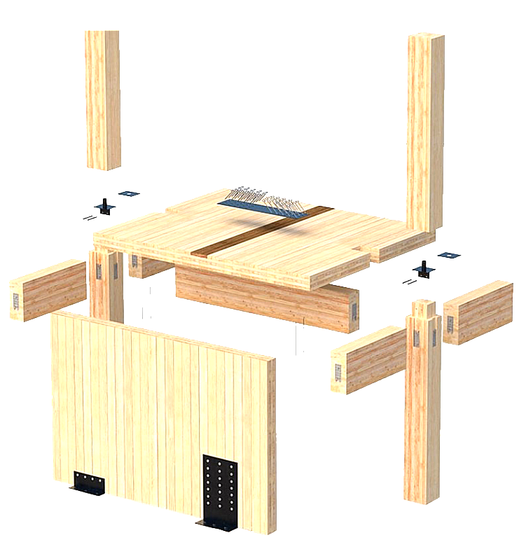
Angle brackets

The standard connector for wall-to-floor and wall-to-foundation joints, transferring in-plane shear. Proprietary CLT angle brackets are rated for specific shear and tension capacities and are selected based on the required resistance at each location. Brackets are typically installed on the interior face of the wall (or concealed in false floors or wall cavities) to maintain a clean exterior and protect them from fire.

Hold-down anchors 

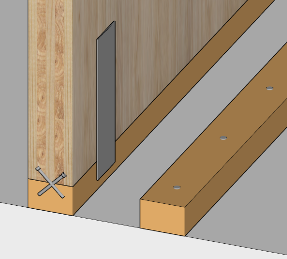
Resist uplift and overturning at the base of shear walls. These may be proprietary heavy-duty systems or adapted from light timber framing practice (per AS 1684), depending on the loads involved. The panel's thickness and layer orientation should be considered for anchor design.

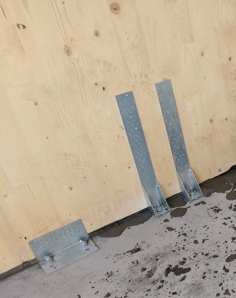
Angle and Hold Down Brackets

Figure 3: Hold down and angle brackets paired together on an Australian site.

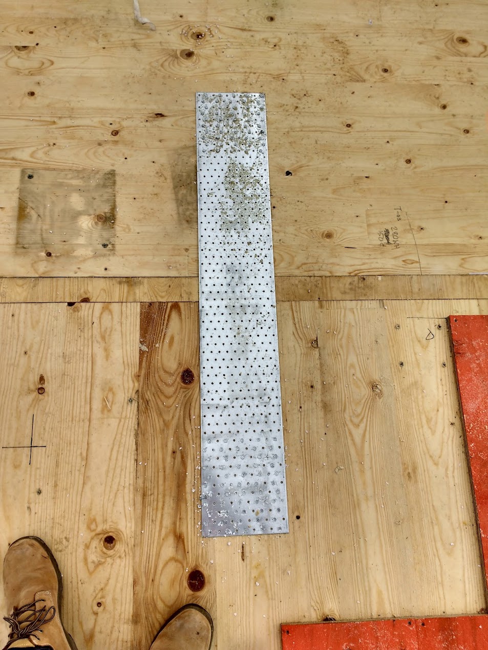
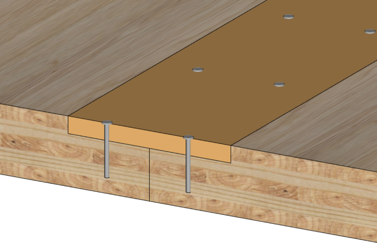
Flat straps and plates 

Join panels in-plane - for example, a steel plate screwed across a wall butt joint to resist tension, or a continuous strap tying floor panels together for diaphragm continuity.

Flat Strap
Flat Strap

Figure 4: Flat plate to tie a floor diaphragm together

Knife plates (embedded steel plates with bolts or dowels) are common in glulam beam-to-column connections and can be used in CLT as well. A steel plate fits into a CNC-routed slot in the panel edge, creating a concealed connection. Wood plugs over bolt heads provide fire protection and a clean finish.

Concealed two-part connectors

Installed in CNC-machined pockets in both joining members and mate on site. They can carry heavy loads and keep all metal hidden - beneficial for both fire performance and aesthetic quality.

When using steel hardware in CLT, fire protection is a key consideration. Exposed steel loses strength at elevated temperatures and can cause premature failure in a fire-rated assembly. Detailing options include recessing steel behind fire-rated linings, applying intumescent coatings, covering with timber plugs, or designing connections with sufficient embedment depth to maintain capacity during the required fire resistance period. Corrosion protection (galvanising or stainless steel) is also important for any connectors exposed to moisture during construction or in service.

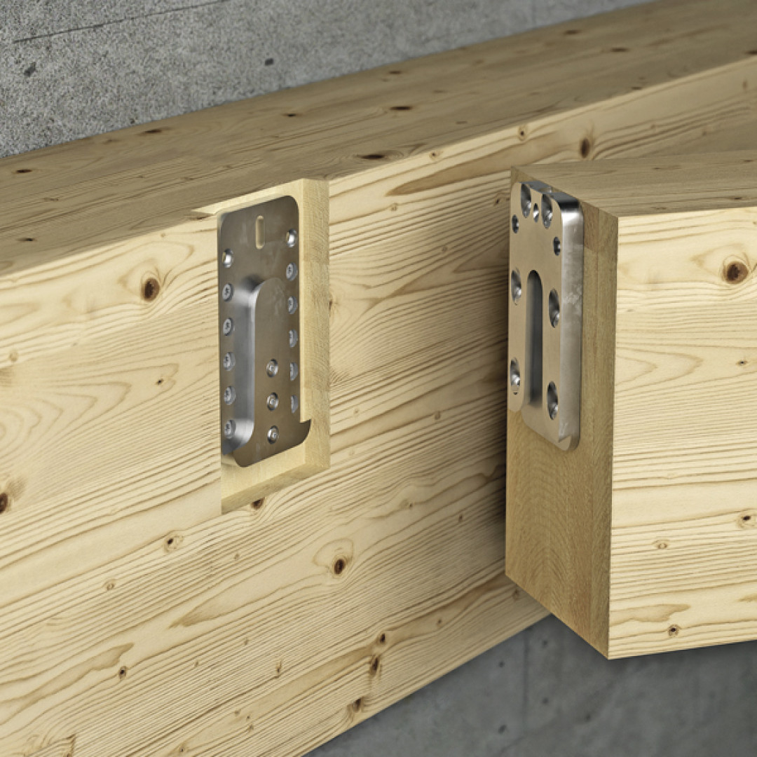
Concealed Connector Rothoblaas

Figure 5: Concealed connectors. Source: Rothoblaas

Nails, Bolts, and Dowels

Traditional nails are not widely used in CLT structural connections because they lack the withdrawal strength that screws provide, and are not suited to modern methods of fabrication. Nails may be used to attach metal hardware (joist hangers, brackets) where lateral loading governs. Driving nails into narrow panel edges (end grain) for withdrawal resistance is generally prohibited by design codes.

Bolts and dowels are used for steel plate connections and heavy-duty joints. Bolted connections should account for the cross-layer layout - predrilling slightly oversized holes can prevent splitting, and steel washers or plates may be needed to distribute forces across the surface lamella.

Innovative and Proprietary Systems

Mass timber connection technology continues to evolve. Notable developments include glued-in rods (steel rods epoxied into pre-drilled holes, creating high-capacity concealed connections - used in Europe for moment connections and CLT-to-concrete anchoring, but not yet standardised in Australian codes), proprietary snap-fit connectors (metal connectors that lock together on site, allowing rapid assembly with hidden hardware), and timber dowel connections (eliminating metal fasteners entirely - used in some European CLT buildings for sustainability and fire performance reasons).

When using any proprietary system, ensure it has relevant technical approvals or test data (European Technical Approvals, or CodeMark certification in Australia) to satisfy engineers and building certifiers. As a general rule, simpler connection palettes produce better outcomes. Many successful CLT buildings have been built with just three connection types - self-tapping screws, angle brackets, and hold-downs - applied consistently and well detailed.
 

Panel-to-panel joints - where one CLT panel meets another in the same plane - are among the most frequently occurring details in a CLT building. The joint profile affects structural capacity, fabrication complexity, dimensional tolerance, and acoustic and fire integrity. Joint type should be selected early and matched to the structural, acoustic, and fire requirements at each location.

Cover-Board (Surface Spline) Joints

A secondary piece - typically plywood or LVL - is fixed across the panel seam. A shallow rebate is CNC-cut along the meeting edge of each panel, and the spline is inserted or attached on site, spanning both panels. Screws or nails through the spline transfer in-plane shear between panels.

Cover-board joints are simple and standardisable: they require only top-side machining and can be applied consistently to all panel edges. They do not reduce the effective width of the floor panel. However, they rely on tight fit for fire and acoustic integrity - any gaps should be sealed with fire-rated caulk or acoustic sealant. The spline must be applied on site, and if machining is required on the opposite panel face (e.g. for a ceiling-side rebate), panel flipping during manufacture adds cost.

Figure 6: CLT Spline joint

Pros

  • Simplicity - they require only top-side machining and can be standardized for all panel edges.
  • Doesn’t reduce effective width of the floor panel
  • Allows for flexible floor panel installation - the panels do not need to be laid in a certain direction.

Cons

  • Relies on tight fits for fire/acoustic integrity; any gaps should be sealed with fire-rated caulk or acoustic sealant.
  • Plywood must be applied on site.
  • Machining from one side means that if machining is required on the opposite side, panel flipping is involved - incurring additional machining cost.

Half-Lap Joints

Each panel edge is milled to half its thickness over a short length, so that overlapping panels interlock flush. Panels are secured through the lapped portion with self-tapping screws for both shear and uplift capacity. Half-laps are commonly used in long wall panels and at diaphragm joints requiring uplift resistance.

Half-laps provide a positive mechanical connection capable of transferring modest bending or tensile forces across the joint, and are straightforward to assemble on site. However, they require machining from both sides of the panel and produce waste material, which results in a reduction in effective panel width equal to twice the lap distance. Panel tolerances must be excellent to create a clean mating - and swelling following wetting during construction can create a step in the panel surface where panels meet. Where high forces are expected, angled screw reinforcement may be added to prevent splitting.

Figure 7: CLT Half-Lap joint

Pros

  • Half-laps provide a positive mechanical connection capable of transferring modest bending or tensile forces across the joint.  
  • Less on-site work

Cons

  • Additional milling is required (from both sides of the panel) and wasted material in the removal, which results in a reduction in effective panel width to the distance of the half-lap, doubled if the half-lap is applied to both sides of the panel.
  • Panel tolerances in machining must be excellent to create a perfect mating of the panels, and swelling following wetting has the potential to create a step in the panel surface where they meet.

Butt Joints with Mechanical Fasteners

The simplest joint - panels meet square-cut, edge-to-edge, with no overlap or profiling. Butt joints have no inherent strength or alignment and rely entirely on connectors (screws, steel plates, brackets) to transfer loads.

Butt joints are quick and simple, reinforced with fixings on site. However, they tend to form gaps due to shrinkage or tolerance accumulation, which can compromise acoustic or fire barriers. Butt joints are suitable where loads are low and other joint methods are impractical, but are generally not preferred for primary structural joints or fire-rated assemblies.

Figure 8: CLT butt joint with mechanical fasteners

Pros

  • Simple, and reinforced with fixings on site

Cons

  • Tend to form gaps due to shrinkage or tolerances, which can compromise acoustic or fire barriers

Joint Selection Considerations

The choice of joint type at each location should consider the structural loads to be transferred (shear, uplift, bending), fire rating requirements (lapped or splined joints provide better fire integrity than butt joints), acoustic separation requirements (joints in separating floors or walls require sealing and may benefit from resilient interlayers), fabrication constraints (single-side vs double-side machining, CNC programming), and site tolerance and fit (half-laps are sensitive to dimensional accuracy; cover-boards are more forgiving).

Platform vs Balloon Construction

Two construction approaches are used for multi-storey CLT buildings, and the choice fundamentally affects connection detailing at every floor level.

Platform construction

Platform construction iss the more common approach. Walls of each storey sit on the floor panel of that level - the floor acts as a platform for the next set of walls. Floor-to-wall connections occur at every level, and load is transferred through bearing at each floor. Platform construction is simpler to detail and to seal for fire and acoustic performance (the floor sits on the full wall thickness, creating a natural fire stop). However, through-thickness compression of the CLT floor panel under vertical load must be accounted for - particularly in taller buildings where cumulative compression across multiple levels affects floor-to-floor heights.

Balloon construction

Balloon Construction uses continuous walls that run past intermediate floors. Floor panels are hung off the side of the wall using hangers, ledgers, or brackets. Balloon framing avoids the through-thickness compression issue and maintains wall continuity for lateral resistance, but requires more complex floor-to-wall hardware and is harder to seal at floor levels for fire and acoustics. In CLT buildings, balloon construction is most commonly seen where CLT floor panels meet continuous concrete core walls.

Figure 9: Platform construction (left), and Balloon construction (right)

Figure 10: Mjøstårnet’s construction showing the choice to use balloon framing for the core

Figure 11: An illustrative example of platform framing, concrete anchors, damp-proof-membranes, and temporary bracing

Wall Plates/Sills

At the base of the ground-floor walls (or any CLT wall bearing on concrete or steel), it is good practice to introduce a sill plate or continuous sole plate. A timber sill (often a treated timber plate) between CLT and concrete:

  • Provides a level surface;
  • Allows easier anchoring (anchor bolts through the sill), and;
  • Acts as a moisture break between concrete and the CLT panel.

Figure 12: Wall plate on the concrete level

The bottom of any CLT wall must not bear directly on concrete without a separation; a damp-proof course or membrane is also placed to prevent moisture ingress. Hold-down anchors or brackets are then used to tie the wall to the foundation through this sill. In many cases, standard heavy-duty hold-downs (used in light timber framing per AS 1684) or epoxy-set anchors can be adapted to CLT – the panel’s thickness and layer orientation should be considered for anchor design. Each project should specify the wall-to-floor panel connection method and spacing; suppliers often have tested details for these (e.g. screws at certain spacing, specific angle brackets, etc.) to achieve shear and uplift capacities.

Wall-to-Wall Connections - Vertical Stacking

In platform construction, an upper-storey wall sits on the CLT floor slab, which in turn bears on the wall below. The walls of successive floors are not directly touching - the floor diaphragm separates them. Where alignment or additional load transfer is needed, connection options include short embedded threaded rods or steel dowels projecting from the top of the lower wall into pre-drilled holes in the upper wall (acting as alignment pins and resisting shear), long timber screws driven at an angle from the inside face of the upper wall down through the floor and into the lower wall, and timber cleats - a dimensional lumber or LVL piece let into a pocket at the top of the lower wall, against which the upper wall is positioned and screwed from both sides. The cleat locks panels in alignment, hides hardware, and provides positive shear transfer. It also simplifies erection by automatically guiding the upper panel into position.

When stacking panels, a strip of fire-rated sealant or mineral wool should be placed at the interface for fire stopping where required. Manufacturers may have proprietary metal connectors (half-lapped steel plates, concealed pins) for wall stacking - always follow tested details to ensure the required resistance is achieved.

Wall-to-Wall Connections - Horizontal Splices and Corners

CLT walls longer than the transportable panel size are made by joining multiple panels along their vertical edges. These vertical panel-to-panel wall joints often use similar profiles to floor joints: half-laps, splines, or butt joints with screws. For straight wall runs, a half-lap joint screwed together creates a flush exterior and is structurally effective. Internal splines maintain full wall thickness externally and are easier to fabricate (groove from one side of each panel). External steel plates are possible but may conflict with finishes and fire requirements - concealed solutions (splines, half-laps, screws) are preferred.

At corners and T-intersections, tight fit is essential - even small gaps can transmit sound, smoke, or fire. Options include a butt joint with concealed steel angle brackets on the inside face, a half-lap corner providing better fire resistance and aesthetics, and a cleated T-joint where a vertical timber cleat attached to one panel fits into a notch in the intersecting panel and is screwed from both sides. Self-tapping screws driven directly through the T-intersection are also effective and simpler to install.

All wall joints should be sealed with compressible foam gaskets or sealant to ensure airtight and sound-tight seams. Stagger vertical joints on adjacent walls in multi-storey corners for stability - avoid four-way joints lining up through consecutive floors.

CLT panels themselves are massive and highly impermeable to air. This is especially the case for CLT from 5+ lamellas, with edge glued boards. Some manufacturers have demonstrated airtightness to passive house standards.

The joints between panels can be weak points for sound, smoke, fire, and moisture if not properly sealed. Even a few millimetres of gap can allow sound leakage, create a path for water, or permit smoke and flame spread. Every joint should be detailed to match the integrity of the solid panel field.

Figure 13: Gap seal within a CLT half-lap floor joint

Acoustic Sealing

In multi-residential and commercial buildings, flanking noise - sound bypassing the rated assembly through structural gaps - can severely undermine the acoustic performance of a CLT floor or wall. Flanking paths through panel joints are one of the most common causes of field acoustic performance falling short of laboratory ratings.

To control flanking, apply continuous beads of acoustic sealant (non-hardening, flexible caulk) along panel joints before panels are drawn together. Alternatively, compressible elastomeric gaskets or foam tapes can be pre-applied to panel edges so that installation compresses the gasket and seals the gap. Research has shown that thin elastomer interlayers in CLT joints can significantly improve acoustic isolation by dampening vibrations and blocking airflow.

Designers should specify all interface sealing requirements on drawings - for example, "Apply continuous acoustic sealant at all panel-to-panel junctions in party walls and floors." On site, quality control is needed to verify that sealants or gaskets are installed as specified before panels are closed in. A well-detailed CLT floor or wall - with sealed joints and appropriate insulation layers - can meet and exceed NCC acoustic separation criteria. For detailed guidance, see CLT Acoustic Design and WoodSolutions Technical Design Guide 44.

Fire Sealing

Panel-to-panel connections are often the weak point in fire tests. Integrity failure can occur if joints open under heat exposure and flames pass through. Fire sealing measures include profiling joints (laps and splines provide better inherent fire integrity than butt joints), applying fire-rated caulk or intumescent sealant at all joints within fire-rated assemblies, placing mineral wool strips at interfaces, and positioning joints away from direct fire exposure where possible (e.g. locating the spline or lap on the side not exposed to fire).

The NCC requires that if an element (wall, floor) has a fire resistance level (FRL), its connections must not reduce that performance. Detailing should recess steel plates, cover bolt heads with timber plugs, or apply fire-rated sealant to delay heat transfer to metal components. For detailed guidance, see CLT Fire Performance.

Moisture and Air Sealing

For exterior walls and roofs, weather tapes or membranes should be applied over CLT panel joints to prevent rain penetration during construction. Self-adhering flashing tape stretched over horizontal and vertical seams provides a waterproof seal that accommodates timber movement. Some CLT suppliers offer proprietary split-release tapes applied to panel edges at the factory, which are pressed into place over the joint once panels are assembled on site.

Sealant within the joint itself forms a first line of defence against both water and air leakage. Airtightness matters beyond energy efficiency - air leakage paths can carry moist interior air into panel interfaces, creating condensation risk within the assembly.

During construction, exposed panel edges (particularly end grain at wall tops and floor panel ends) should be covered to prevent water seeping into joints and causing swelling. Once the building is enclosed, any moisture that entered joints during the open-structure period should be allowed to dry - avoid trapping water in joints with non-breathable sealants or finishes applied before the timber has dried. For construction-phase moisture management, see Moisture Management in Mass Timber Construction.

Gap Control on Site

Gap size is controlled primarily by CNC fabrication tolerances, but site conditions also influence fit. Panels should be drawn tight using come-alongs (ratchet straps) or panel alignment bars hooked into pre-cut holes or panel edges. Panels should never be forced into position with excessive pressure - if something isn't fitting, stop and check dimensions, debris, or rotation.

A small designed gap (1-3 mm) is typically included at certain joints to allow ease of fit and to prevent a run of slightly oversized panels from compounding tolerance across the floor plate. Where timber arrives at lower MC (e.g. 8-10%) and takes on moisture on site, panels may expand slightly. Some designs include a deliberate expansion gap every few panels, or at the floor perimeter, sealed after installation. Any intentional gap should be specified in the design, not improvised on site.

Modern CLT buildings frequently combine CLT panels with concrete cores, steel frames, glulam beams, or light timber framing. These cross-material interfaces require careful detailing to account for different material properties, tolerances, and behaviour under fire, moisture, and long-term loading.

CLT to Concrete

The most common scenario is CLT walls or floors connecting to a concrete slab, foundation, or core wall. The primary strategy is steel connectors anchored into the concrete and screwed or bolted to the CLT - for example, cast-in anchor bolts aligning with a steel angle or plate, which is then fixed to the CLT with screws. Alternatively, steel plates epoxied into the concrete can mate with CNC-cut slots in the CLT (knife plate connections).

Key considerations include providing a moisture break between concrete and CLT (damp-proof course, membrane, or treated timber sill - timber should never bear directly on concrete), using slotted holes or adjustable brackets to accommodate the tolerance mismatch between CNC-cut CLT (±2 mm) and in-situ concrete (±10-15 mm), and in seismic designs, using ductile steel connectors that yield under extreme loads to prevent the CLT from splitting.

CLT floor diaphragms connecting to concrete cores typically use embed plates in the core face, with screws or brackets fixing the CLT to the plate. These connections transfer lateral loads (wind and seismic) into the core. Where forces are high, shear keys or toothed plates can supplement screw connections.

CLT to Steel Frames

When CLT panels interface with steel beams or columns, connections typically use steel-to-steel attachments combined with timber screws. Common details include a steel top flange plate welded to the beam, with screws driven down through the plate into the CLT (acting as a ledger), angle brackets on the side of the beam clamping the CLT panel, and knife plates extending from a steel column into a CNC-routed slot in the CLT panel edge, bolted or doweled in place and concealed with timber plugs for fire protection.

Differential movement must be considered. CLT may shrink slightly in thickness over time and with moisture changes, whereas steel dimensions remain stable. In multi-storey buildings where CLT panels are stacked between steel floors, vertical shrinkage of a few millimetres per level can accumulate. Accommodate this with slotted connections or adjustable support seats. The stiffness mismatch also means steel will attract more load if connected rigidly to CLT - a degree of flexibility (long slotted holes, bearing pads) can relieve stress concentrations.

For fire compliance, steel beams supporting CLT floors may need fire protection even where the CLT panel itself has adequate charring capacity. A steel member can reach failure temperature well before the timber, causing connection failure. Designing CLT floors to rest on steel (gravity support) while using separate bracing systems for lateral loads is one strategy to decouple systems and simplify fire design.

CLT with Glulam or LVL Elements

CLT panels are commonly combined with glulam (GLT) or LVL beams and columns - particularly for gravity systems or where long spans exceed CLT's efficient range. Connections are timber-to-timber but typically still use steel hardware.

A CLT floor sitting on a glulam beam can be connected with self-tapping screws driven at angles through the CLT into the beam. Multiple inclined screws in a row can create a force couple providing diaphragm continuity. Proprietary face-mount hangers sized for CLT panel thickness are also available, similar in concept to joist hangers but scaled for mass timber.

Since all members are timber, differential shrinkage is less problematic than at steel or concrete interfaces - provided members have similar MC and grain orientation is understood (cross-grain CLT behaves differently from long-grain glulam). For heavy point loads from beams bearing on CLT walls, bearing stiffeners or hardwood plugs can be inserted to locally reinforce the compression zone and prevent crushing of the surface lamella.

CLT with Light Timber Framing

CLT panels work well alongside conventional light timber framing. Common interfaces include a timber-framed wall sitting on a CLT floor (the CLT acting as a platform, similar to a rim joist), a CLT wall anchored to a timber-framed floor via metal straps to the floor framing, and non-loadbearing timber-framed partitions within a CLT structural shell, fixed with standard framing brackets.


These interfaces can generally be treated like standard platform framing details. Use coach screws or structural screws rather than ordinary nails when connecting into the side grain of CLT from framing members.

Services coordination is one of the most important - and most commonly underestimated - aspects of CLT building design. CLT panels are solid timber plates: there is no cavity to run services through. Every service route must be planned, coordinated, and in many cases CNC-machined into the panels before they leave the factory.

Routing Strategies

CNC-routed channels

Shallow channels (typically 30–50 mm deep) machined into the panel face during manufacture, used for electrical conduit, small-diameter pipework, and data cabling. Channel depth is limited by the panel's structural capacity - routing into major-axis lamellae reduces bending strength. Channel locations must be coordinated with the structural engineer and included in shop drawings.

Figure 14: Routed channel on the surface of a CLT wall to track electrical conduit

Suspended ceilings

Service zones created below the CLT floor panel, providing the most flexible strategy for horizontal services distribution (electrical, mechanical, hydraulic, fire sprinkler) and space for acoustic treatment and fire protection linings. Common in commercial and institutional buildings.

Raised floors

Service zones above the CLT floor panel, used primarily for electrical and data distribution in commercial buildings. Also allows for underfloor heating and cooling systems.

Dedicated service walls and risers

Timber frame or steel stud walls positioned adjacent to CLT structural walls, providing a cavity for vertical services distribution without penetrating the CLT panel. Service risers for wet areas (bathrooms, kitchens, laundries) are typically framed separately from the CLT structure to allow maintenance access and isolate plumbing noise.

Surface-mounted services

Conduit, trunking, and pipework fixed directly to the CLT surface. Common in industrial, warehouse, and some commercial applications where expressed services are architecturally acceptable.

Figure 15: Surface-mounted services 

Coordination Requirements

Services coordination in CLT buildings requires early involvement of the services engineer (hydraulic, electrical, mechanical, fire) in the CLT panel layout process, a fully coordinated services model (BIM or equivalent) before shop drawings are finalised, identification of all panel penetrations: risers, branch connections, floor wastes, downpipes, sprinkler drops. All of these need to be incorporated into CNC fabrication drawings, and structural verification of any CNC-routed channels or penetrations that affect panel capacity.

Late-stage additions foul the prefabrication advantages of using CLT. Drilling penetrations on site through CLT panels - should be avoided wherever possible. Site-drilled penetrations may compromise structural capacity, fire resistance, or acoustic performance, and cannot be rectified with the precision of factory machining.

Wet Area Coordination

Bathrooms, kitchens, and laundries require particular attention. Floor set-downs for waterproofing and drainage may need to be built into the CLT panel geometry (thicker panels or step details), or achieved using raised floor systems with waterproof membranes above the CLT.

Plumbing penetrations through CLT floors should be sleeved to allow for through-thickness movement and to maintain fire and acoustic separation. Flexible connections are recommended at floor penetrations to accommodate differential movement between the CLT structure and rigid pipework.

CLT panels are manufactured with CNC machinery to tight dimensional tolerances - typically ±2 mm on length, width, and thickness. This precision is one of the product's strengths, but it creates challenges at interfaces with less precisely constructed elements.

Interface Tolerances

The most common tolerance issues occur at CLT-to-concrete interfaces (in-situ concrete tolerances are typically ±10–15 mm, significantly larger than CLT), CLT-to-steel interfaces (steel fabrication tolerances are tighter than concrete but erection tolerances add variation), and CLT-to-glazing interfaces (curtain wall and window systems require consistent opening dimensions - deviations affect seal performance and thermal bridging).

Managing Tolerance

Practical strategies include shimming and packing at bearing interfaces to accommodate level differences (ensure supports are level and true before panel placement - keep level variance under approximately 5 mm across a panel footprint), adjustable connections (slotted holes, adjustable brackets) that allow alignment correction during erection, setting-out protocols that establish reference points before CLT installation begins, survey and verification of supporting structure before CLT delivery to confirm actual dimensions against design, and tolerance allowances built into CNC fabrication (slightly oversized openings, adjustable rebates).

Tolerance protocols should be agreed between the design team, CLT manufacturer, and builder before fabrication. The critical interfaces should be identified, the acceptable tolerance range at each interface documented, and the responsibility for shimming, packing, or adjustment assigned.

Cumulative Movement in Multi-Storey Buildings

Through-thickness shrinkage of CLT floor panels accumulates over multiple levels. A 200 mm panel experiencing approximately 2 mm of thickness change per level will produce 10-16 mm of cumulative movement over 5-8 storeys. This affects floor-to-floor heights, façade connections, services risers, and stair alignments. Cumulative tolerance should also be monitored during erection: if each level is off by 3 mm, by level 8 the cumulative deviation may affect façade connections and vertical alignment.

Through-thickness movement should be calculated and accommodated through movement joints, flexible connections at façade interfaces, and sleeved or flexible service connections at floor penetrations. Multi-storey CLT buildings benefit from careful surveying - after installing each floor and the next set of walls, check that walls are plumb and in correct position relative to the grid using total stations or laser levels. Minor adjustments can be made by shimming at the base or using slack in screw holes of brackets before final tightening.
For the underlying dimensional behaviour, see CLT Material Properties and Manufacture.
 

CLT construction follows a different rhythm from conventional building. The erection phase is fast - often 20-30% faster than traditional concrete construction - but this speed depends on thorough preparation, precise logistics, and disciplined site practices.

Erection Sequence

For a given storey, the sequence is typically: place and fix all perimeter and internal wall panels, apply temporary bracing to hold them plumb, then install floor panels that sit on those walls, tying the structure together. Because CLT floors act as diaphragms, getting them in place quickly is critical to stabilise the supporting walls below.

Each panel should be numbered and marked according to an erection drawing so that the crew can identify which piece goes next. Panels typically arrive with pre-installed lifting points or brackets - follow the supplier's guidelines on lifting sling arrangement to avoid panel damage or imbalance.

Crane and Logistics

CLT panels are heavy and large. A typical 5-layer, 200 mm thick panel at 3 m × 8 m weighs approximately 2,400 kg. Crane selection, reach, and capacity must be confirmed against the heaviest and most distant panel lift. Access for delivery trucks (typically semi-trailer length) and crane positioning (outrigger pads, exclusion zones) should be resolved during construction planning.

Panels can often be placed directly from truck to final position if sequencing is planned for just-in-time delivery. This minimises site storage, reduces weather exposure, and keeps the erection programme moving. Where site storage is necessary, panels should be stored off the ground on bearers (minimum 150 mm clearance), under breathable covers with sides open for ventilation. For detailed guidance, see Moisture Management in Mass Timber Construction.

Temporary Stability

During erection, unconnected wall panels must be braced against wind. A bare CLT wall without floors or adjacent returns can be caught by wind loads - temporary braces (adjustable steel props or timber struts) should be designed by the structural engineer for construction-period wind loads. Partially completed floor panels may also need temporary propping for long spans until all design connections are made.

On-Site Fitting

Even with CNC precision, site fitting requires attention. Panels should be pulled tight using come-alongs (ratchet straps) or panel alignment bars - never forced with excessive pressure. If something isn't fitting, check dimensions, debris, or rotation before applying more force. A minor misalignment is usually due to debris in the joint or a slight panel rotation, not a fabrication error.

Panels may arrive at lower MC than site conditions and expand slightly on site. Designed expansion gaps (a few millimetres every few panels, or at the floor perimeter) accommodate this, sealed after installation. Any intentional gap should be specified in the design, not improvised on site.

Sequencing Connectors and Services

Plan when to install connectors: many angle brackets or hold-downs can be partially attached to panels on the ground to reduce work at height - for example, screw a bracket to the bottom of a wall panel while it is on the ground, so that after the wall is stood, the bracket just needs anchoring to the floor. Ensure pre-installed hardware does not interfere with lifting.

Coordinate service penetration sequencing with the erection programme. Large openings for ducts or staircases may require delaying installation of a particular floor panel until equipment is lowered through the opening. Coordinate any special crane picks or rotations in advance.

Weather and Moisture Management

The open-structure period from first panel placement to envelope closure, is the highest-risk window for moisture exposure. Protection measures (taping, wrapping, temporary roofing, rapid drainage) should be planned as part of the construction methodology. Stage construction to limit open timber exposure: after a few levels of CLT have been erected, start installing permanent façade on the lower levels. The mantra is "roof on, walls on, as soon as practical."
For detailed guidance, see Moisture Management in Mass Timber Construction.