CLT Fire Performance

Timber burns. This is understood, and it is not the end of the conversation - it is the beginning. The fire performance of CLT buildings is well documented, well tested, and routinely demonstrated to meet and exceed NCC requirements across a range of building types and heights.

CLT's fire behaviour is governed by a simple and predictable mechanism: charring. As the outer surface of a panel burns, it forms an insulating char layer that slows the rate of section loss and protects the structural timber beneath. This predictable behaviour is the basis for fire engineering calculations that determine fire resistance levels (FRLs) and inform compliance strategies.

Fire performance in CLT buildings depends not on the panel alone but on the complete assembly: panel thickness, encapsulation strategy, connection protection, joint detailing, and the interaction between fire engineering and architectural decisions about which surfaces are expressed and which are lined.

This article covers the charring mechanism, fire resistance assessment, encapsulation strategies, NCC compliance pathways, and the practical detailing considerations that support confident fire design. For the broader context of fire safety in timber buildings, see WoodSolutions Technical Design Guide 17: Fire Safe Design of Timber Structures and the Insurance Guide.

Key Takeaways

  • CLT chars at a predictable, well-documented rate. The char layer insulates the timber beneath, maintaining structural capacity for extended periods. This predictable behaviour is the basis for all fire engineering calculations in CLT construction.
  • Fire performance is a property of the assembly, not the panel alone. Panel thickness, encapsulation (plasterboard lining), connection protection, joint sealing, and compartmentation all contribute to the building's fire resistance.
  • CLT can achieve fire resistance levels of 60, 90, and 120+ minutes through tested and engineered solutions meeting NCC requirements for buildings up to and including the tallest timber structures currently constructed in Australia.
  • Two compliance pathways exist under the NCC: Deemed-to-Satisfy (DtS) solutions using fire-rated encapsulation, and Performance Solutions using fire engineering assessment. Exposed (unlined) CLT typically requires a Performance Solution.
  • Adhesive behaviour during fire is product-specific and affects charring calculations. Some adhesive systems maintain bond integrity behind the char front; others may delaminate, potentially accelerating charring. This is a key reason CLT products are not interchangeable for fire-rated applications.
  • Sprinkler systems, detection, and compartmentation work alongside CLT's inherent fire performance. Fire design for CLT buildings follows the same risk-based framework as for any other structural material.
     

Publications

1. How CLT Behaves in Fire

The Charring Mechanism

When CLT is exposed to fire, the outer surface ignites and begins to char. The char layer that forms is a poor conductor of heat - it insulates the unburnt timber beneath, slowing the rate at which the fire front advances into the panel cross-section. Behind the char front, a thin zone of heated but uncharred timber (the "pyrolysis zone") experiences some reduction in strength and stiffness, but the timber beyond this zone remains at or near ambient temperature and retains its full structural properties.

This behaviour is fundamentally different from steel, which loses strength progressively as temperature rises throughout the section, and from concrete, which can spall under intense heat. Timber's charring behaviour is predictable, measurable, and calculable. It forms the basis of all fire resistance assessment for CLT.
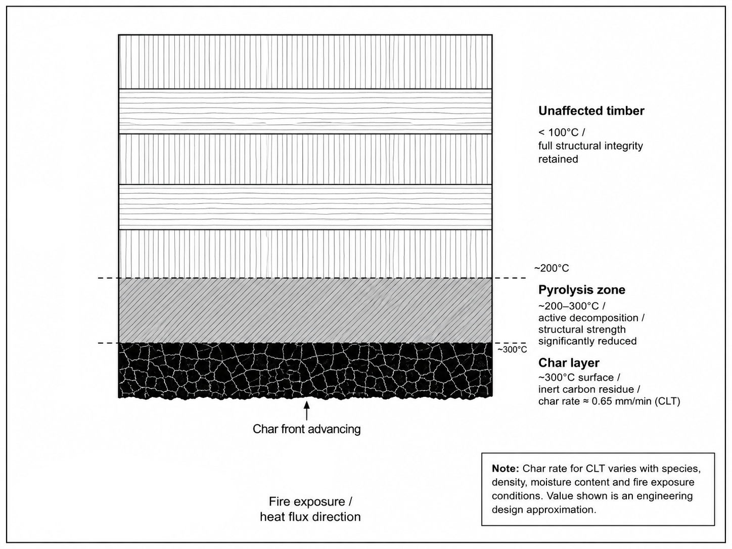
Figure 1: Char diagram of a section of CLT

Charring Rate

The rate at which char advances into the panel is called the charring rate, typically expressed in millimetres per minute (mm/min). For most softwood CLT products, the nominal charring rate is approximately 0.65 mm/min, though the effective charring rate (which accounts for the reduced-strength pyrolysis zone) is higher (typically around 0.7-0.8 mm/min depending on the calculation method and standard applied).

The charring rate is influenced by timber density (denser species char more slowly), lamella thickness (thinner lamellae reach the glue line sooner), adhesive type (see Section 2 below), panel orientation (edge-of-panel exposure may char faster than face exposure), and fire intensity and ventilation (standard fire curves assume a specific time-temperature profile).

Residual Section and Structural Capacity

Fire resistance assessment for CLT works by calculating how much of the panel cross-section remains uncharred after the required fire exposure period, then verifying that the residual section has sufficient structural capacity to carry the applied loads.

For a 200 mm, 5-layer CLT panel exposed to fire on one side, with a charring rate of 0.65 mm/min, approximately 39 mm of timber is consumed in 60 minutes and 59 mm in 90 minutes. The residual section (uncharred timber) continues to carry loads. Thicker panels and more layers provide greater fire endurance, and the margin can be designed to achieve 60, 90, or 120+ minutes of fire resistance.

Why Firefighters Value Timber's Behaviour

CLT's fire behaviour has a practical advantage from an emergency response perspective: timber structures give audible and visible warning before failure. Charring, cracking, and deflection are observable indicators of progressive section loss. This contrasts with steel structures, which can fail suddenly and without warning when the steel reaches its critical temperature, and with concrete structures, where spalling and reinforcement exposure may not be visible until shortly before collapse.
 

Adhesive behaviour during fire is one of the most significant variables in CLT fire engineering, and one of the primary reasons CLT products are not interchangeable between manufacturers for fire-rated applications.

Adhesive Behaviour at Glue Lines

As the char front advances through a CLT panel, it periodically reaches a glue line - the boundary between adjacent lamellae. What happens at that boundary depends on the adhesive system:

Adhesives that maintain bond integrity: Some adhesive systems (notably certain MUF formulations) maintain their bond strength at temperatures behind the char front. The char advances through the glue line without delamination, and the charring rate remains relatively constant across the panel's full thickness. Fire engineering calculations can use a single, consistent charring rate.

Adhesives that delaminate: Other adhesive systems (some PUR formulations) may lose bond strength at elevated temperatures before the timber itself has charred. This can cause the charred lamella to detach (delaminate), creating two  effects:

  1. Uncharred timber is exposed to direct flame. The newly exposed surface then chars at a faster initial rate until a new insulating char layer forms. This uncharred 'fresh' timber also contributes to the fire behaviour itself.
  2. The detached / delaminated layer of timber adds fuel to the fire, changing the behaviour of the fire itself in an undesirable way.

The result is an increased charring rate - the fire consumes more timber per unit time than a single-rate calculation would predict.

Implications for Design

This adhesive-dependent behaviour means that fire resistance calculations must use the charring rate data specific to the CLT product being specified, including its adhesive system. Generic charring rates may underestimate section loss for products with adhesives prone to delamination, or overestimate section loss for products with heat-stable adhesives.

The adhesive behaviour data is obtained through fire testing - it cannot be reliably predicted from the adhesive's material properties alone. This is why manufacturer-specific fire test reports are essential for any fire-rated CLT application, and why substitution between CLT suppliers requires re-verification of fire performance.
 

Fire resistance in CLT buildings is assessed and expressed using the same framework as for any other structural material — Fire Resistance Levels (FRLs) defined in terms of structural adequacy, integrity, and insulation.

FRL Components

An FRL is expressed as three numbers , e.g. FRL 90/90/90, representing:

  • Structural adequacy: The time (in minutes) the element continues to carry its design load during fire exposure. For CLT, this is determined by the residual section capacity after charring.
  • Integrity: The time the element prevents the passage of flames and hot gases through gaps, cracks, or openingsFor CLT, this depends on joint detailing, penetration sealing, and the prevention of burn-through at panel edges and connections.
  • Insulation: The time the element limits temperature rise on the unexposed face to acceptable levels. For CLT, this depends on panel thickness and any additional lining or insulation layers.

Assessment Methods

Fire resistance can be demonstrated through full-scale fire testing (furnace testing of representative assemblies to the standard fire curve), calculation methods (using published charring rates and residual section analysis using AS 1720.4 or Eurocode 5 Part 1-2), or a combination of testing and calculation supported by fire engineering analysis.
Full-scale testing provides the most direct evidence but is expensive and product-specific. Calculation methods are widely used for structural adequacy assessment but may need to be supplemented by testing for integrity and insulation, particularly for complex joint configurations.
 

Encapsulation - lining CLT panels with fire-rated plasterboard - is the most common strategy for achieving fire resistance in CLT buildings. It is the basis of most Deemed-to-Satisfy (DtS) solutions and is also used in Performance Solutions where partial encapsulation is combined with exposed timber.

How Encapsulation Works

Fire-rated plasterboard linings delay the onset of charring by shielding the timber surface from direct heat and flame exposure. The plasterboard absorbs heat and releases chemically bound water (a process called calcination) before it eventually fails, at which point the timber behind it begins to char.

The combined fire resistance of the assembly is the sum of the protection period provided by the plasterboard lining and the charring resistance of the CLT panel behind it.

Encapsulation Configurations

Common configurations include full encapsulation (all CLT surfaces lined with fire-rated plasterboard - this provides the highest level of fire protection and is the standard DtS approach), partial encapsulation (some surfaces lined, others exposed - for example, CLT ceilings left exposed while walls are lined, or vice versa), and no encapsulation (all CLT surfaces expressed- this typically requires a Performance Solution with fire engineering assessment).

The choice between full, partial, and no encapsulation is driven by the required FRL, the NCC compliance pathway, the architectural intent (expressed timber versus conventional finishes), and the fire engineering strategy (sprinkler provision, compartment size, egress design).

Lining Specification

Fire-rated plasterboard linings must be specified and installed in accordance with the lining manufacturer's tested systems. Key considerations include board thickness and number of layers (typically 1 or 2 layers of 13–16 mm fire-rated plasterboard), fixing method and spacing (screw type, length, and spacing affect the lining's ability to remain in place during fire exposure), joint treatment (taped and sealed to maintain integrity), and integration with acoustic treatment (fire-rated linings often serve a dual acoustic and fire function - resilient mounting systems can address both requirements simultaneously).

The National Construction Code provides two pathways for demonstrating fire compliance in CLT buildings: Deemed-to-Satisfy (DtS) Solutions and Performance Solutions.

Deemed-to-Satisfy Solutions

DtS solutions use prescriptive requirements — if the building meets the specified construction details, material types, and FRLs, it is deemed to comply. For CLT, DtS compliance typically requires full encapsulation of all CLT surfaces with fire-rated plasterboard, achieving the required FRL for the building class and rise in storeys, along with compliance with all other DtS provisions for fire separation, egress, detection, and suppression.
DtS solutions provide certainty and simplicity but limit architectural expression — visible timber surfaces are generally not achievable under a DtS approach because the NCC's DtS provisions for fire-protected timber construction require full encapsulation.

Performance Solutions

Performance Solutions use fire engineering analysis to demonstrate that the building achieves the required level of fire safety through alternative means. This pathway allows greater design flexibility (including exposed CLT surfaces) but requires engagement of a fire engineer and acceptance by the relevant authority.

A Performance Solution for a CLT building typically involves fire modelling of the specific building configuration (compartment size, ventilation, fuel load), charring analysis using product-specific test data, assessment of the contribution of exposed timber to fire load and fire development, demonstration that structural adequacy is maintained for the required period, and consideration of sprinkler provision, detection, egress, and firefighting access.

Performance Solutions are project-specific. They require early engagement of the fire engineer, close coordination with the structural and architectural design, and clear documentation for building consent.

Sprinklers

Sprinkler systems are not a substitute for structural fire resistance, but they play an important complementary role in CLT fire design. Sprinklers control fire growth, reduce peak temperatures, and limit the area of timber surface exposed to sustained flame, all of which reduce the demands on the CLT's charring resistance.

In many Performance Solutions for CLT buildings, sprinkler provision is a key element of the fire safety strategy. The NCC's concessions for sprinkler-protected buildings (reduced FRL requirements in some configurations) can be applied to CLT buildings in the same way as for other structural materials.

Fire performance in CLT buildings depends not just on panel thickness and encapsulation but on the detailing of joints, connections, penetrations, and compartment boundaries. These details are where fire resistance is most commonly compromised.

Joint Protection

Joints between CLT panels are potential pathways for fire spread. Joint protection strategies include sealing joints with intumescent sealant or fire-rated gaskets (which expand when heated to close gaps), covering joints with fire-rated plasterboard strips or proprietary joint protection systems, and designing joint geometry to prevent direct flame passage (rebated or lapped joints rather than simple butt joints).

Connection Protection

Steel connections (brackets, plates, bolts) lose strength rapidly at elevated temperatures. Protection strategies include recessing connections behind fire-rated linings so they are not directly exposed to fire, applying intumescent coatings to exposed steel components, designing connections with sufficient timber cover to delay heat transfer to the steel, and using self-tapping screws with adequate embedment depth so that the screw tip remains in cool timber during the fire resistance period.

Penetration Sealing

Service penetrations through fire-rated CLT assemblies must be sealed to maintain integrity and insulation. Penetration sealing systems (fire collars, intumescent wraps, fire-rated sealants) should be tested and certified for use with CLT-specific assemblies — systems tested on plasterboard or concrete may not perform equivalently on timber substrates.

Compartmentation

Fire compartmentation (dividing the building into discrete fire compartments that limit fire spread) follows the same principles in CLT buildings as in any other construction type. Compartment boundaries must achieve the required FRL for structural adequacy, integrity, and insulation. In CLT buildings, particular attention is needed at wall-to-floor junctions where the structural CLT passes through the compartment boundary, at service risers and shafts, and at façade junctions (to prevent external fire spread between levels).

Exposed CLT is one of the most compelling architectural qualities of mass timber buildings, and one of the most significant fire design considerations. The decision to express CLT surfaces has implications that extend well beyond aesthetics.

Fire Load Contribution

Exposed timber surfaces contribute to the fire compartment's fuel load. In a fully developed fire, exposed CLT can continue to burn after the contents of the room have been consumed, potentially extending the duration and intensity of the fire. This contribution must be assessed and managed in the fire engineering analysis.

Strategies for managing exposed timber fire load include limiting the proportion of exposed surface area within each compartment, combining exposed and lined surfaces (e.g. exposed ceiling with lined walls, or vice versa), providing sprinkler protection to control fire development and limit the area of timber surface involved, and demonstrating through fire modelling that the building achieves acceptable safety outcomes despite the exposed timber.

Self-Extinction

An important area of ongoing research is the self-extinction behaviour of CLT, whether, and under what conditions, CLT will stop burning once the external fire source is removed. Self-extinction depends on the char layer thickness, heat flux from the fire environment, ventilation conditions, and panel configuration.

Where a Performance Solution relies on self-extinction, the fire engineer must demonstrate through test evidence or validated modelling, that the specific CLT product and compartment configuration will achieve reliable self-extinction after burnout of the compartment contents.

Practical Design Guidance

For projects seeking exposed CLT, early engagement of a fire engineer is essential. The fire strategy should be developed in parallel with the architectural design, not retrofitted after design decisions about expression have been made. Key early decisions include which surfaces will be exposed and which will be lined, the sprinkler strategy, compartment sizing and layout, and the acceptable proportion of exposed surface area.

Related Content