A truss is a structure comprising one or more triangular units. Each triangle is constructed with straight and usually slender members of timber, connected at the ends by joints. External loads, and the structure's reaction to those loads, act at the joints, resulting in forces that are either tensile or compressive.
The strength of a truss lies in its triangulation of banding members that work together to the advantage of the overall structure. For trusses, compression members often dictate the size of the elements, thus designs that have short compression members or restraint against lateral buckling are generally more efficient than trusses with longer compression members.
Within a building two forms of trusses can be found. Nail plated trusses are trusses hidden from view that use nail plates as connectors. Architectural trusses refer to those attractively detailed timber trusses, exposed to view. This guide focuses primarily on the application process of the latter.
The benefits of timber trusses are notable and numerous. Timber roof trusses are an ecologically sound choice, compared to conventionally pitched roofs, they use smaller dimension timbers that span greater distances and this in turn reduces the total timber volume contained within. Architectural timber trusses are lightweight, enabling speedy and efficient construction and installation that results that in a visual feature to be enjoyed for decades.
This article provides a comprehensive overview to the processes involved in specifying, assembling and installing an architectural roof truss.
Criteria Level: 1
This section outlines the typical connections used in timber truss construction.
Criteria Level: 1.01
Greater truss spacing or reduced web numbers usually cause load increases and in these instances, more or larger toothed plates will be required. Toothed plates are used to bolt a number of identical trusses together. This assists in reducing the connector load and members act collectively to reduce buckling.
Toothed plates are available in a variety of finishes to suit numerous corrosive environments. When finished with a bright epoxy coating the plates can provide a strong visual contrast against stained or clear finished timber. For a more seamless look, plates finished with an opaque paint system will blend well with truss members.
Nails greater than 4mm in diameter require hand nailing or should be rivet gun driven. Plates greater than 3mm thick must be pre-drilled or punched, making gun nailing an unsuitable option.
Criteria Level: 1.02
The thickness of the architectural truss member makes it unsuitable for a simple timber to timber lapped joint. Pneumatically fired gun nails can penetrate 2mm thick steel and thin plates can be placed on the outside of members. Where concealment is requested, it is possible to place plates either in saw kerfs cut into solid timber or between layers for multiple members. This method will greatly increase the joint's strength by introducing a double shear on the nailed joint.
Criteria Level: 1.03
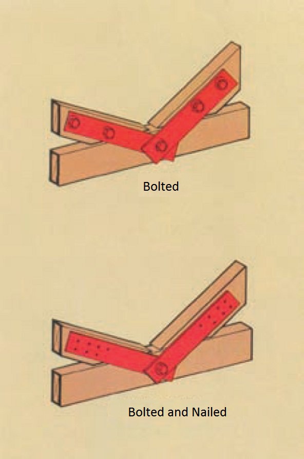
Architectural Trusses can be connected with bolts through overlapping timber members. While multilayered trusses of this type provide a sound structural arrangement, they will not always produce the most visually appealing look.
Acceptable arrangements of multiple member architectural trusses are limited to single webs with double chords, double and single webs with single chords, and double and triple webs with double chords.
A structural advantage of multiple members is that bolts are placed in compound bending, effectively increasing the joint capacity. Compression members may need to be designed as spaced columns to increase their efficiency.
The allowable loads for bolts, as specified in AS1720 Timber Structures Code Part 1: Design Methods, require the use of heavy washers. When a load is applied to a bolted timber joint, the heavy steel washer provides a measure of restraint to both the head and nut, increasing the stiffness and strength of the joint. In all cases heavy washers should be provided whether the bolted connection is a simple timber to timber joint or split ring, or a timber to timber joint interleaved with a steel plate.
Criteria Level: 1.04
For heavily loaded trusses the use of thick steel side plates or gussets is recommended. The load transfer is shifted to the close fitting side plates and this reduces the significance of loads perpendicular to the grain.
When members meet at acute angles the minimum bolt spacing may require the gusset to become long and obtrusive. Note that long gussets can cause concern with secondary stresses, as the rigid joints will not allow rotation. In such cases, high loads perpendicular to the grain, result. Articulated nodes can provide a solution. The figure below is an example.
If there is a preference for plates to be hidden from view, they can be effectively concealed within multi member trusses. Alternatively plates can be painted a neutral colour to blend with the timber. In all cases the bolt heads bear directly against the timber and thus heavy washers must be installed.
Criteria Level: 1.05
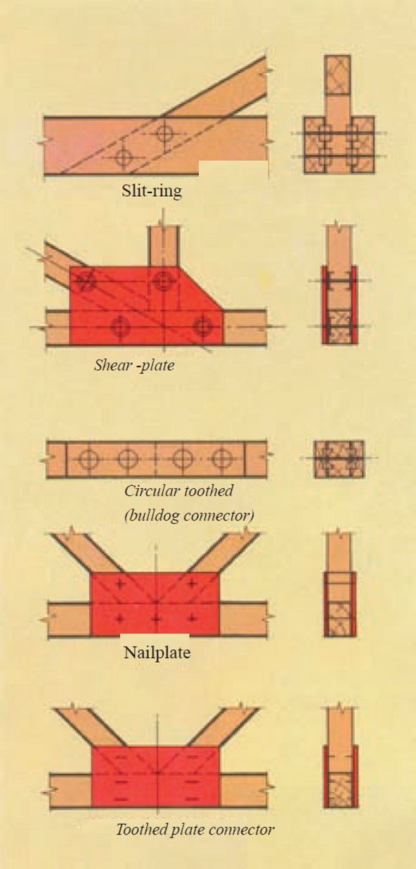
The most common special connector used in trusses is the Split Ring. Suitable for both seasoned and unseasoned timber, it operates as a large bolt that also accommodates some shrinkage of the timber. While typically a more expensive fastener, its main advantage is that within a single row it allows rotation of a joint. Consequently secondary stresses are minimised.
A typical arrangement in a three member joint is one bolt with a pair of Split Rings; either 64mm or 102mm in diameter. In splices, multiple connectors may be used with spacings as detailed in AS1720. The connectors main limitation is that of distance from the bolt to the end of a tension member, especially in unseasoned timber.
The most expensive of all special connectors, Shear Plates are used for the transfer of large forces to steel side plates. The Shear Plate is embedded in a series of grooves specially cut into only the timber. The load is taken from the Shear Plate into the bolt and then into the side plate.
Criteria Level: 1.06
Structural plywood can be used in joining truss members where either the gusset can be applied to both sides of single timber members or where multiple members are used, as single interleaved plates. The aesthetics of the truss will be influenced by the shape and finishing of the plywood gusset.
Criteria Level: 1.07
In the absence of significant reversal of load, such as wind uplift, tension members may be replaced with steel tie rods or cable. If steel tubing is used, often in the form of a telescopic post (for tensioning purposes), it is called a Polconeau truss when pitched or when applied to a straight beam, a Barap truss.
Criteria Level: 1.08
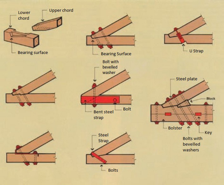
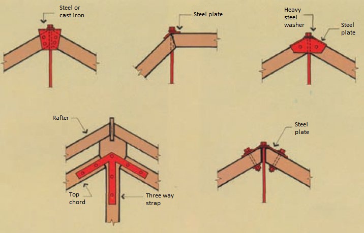
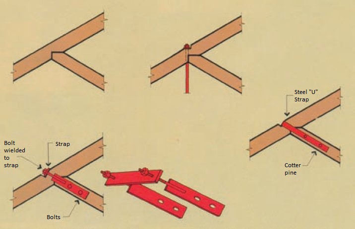
Traditional truss connections require sound carpentry skills as joint loadings are often accommodated without hardware. However, in many instances the use of steel straps can support both function and aesthetics.
In traditional construction, the top chord does not extend beyond the support due to the complications of the highly stressed heel joint. If an eave overhang is required than either a member line with purlins is used or (in applications with secondary framing) the rafters are placed on top of the top chord and cantilevered to form the overhang.
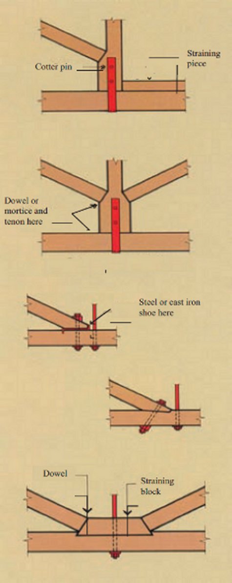
When the tension members of the truss are not subject to bending loads or compression, rod and block arrangements are possible. In these instances, rods can be used for tension members and on occasion as anti sag rods supporting the self-weight of the lower chord. The lower chord itself may be a rod in some configurations.
The figures below provide an overview to traditional carpentry joints.
Criteria Level: 2
In most cases the most efficient structural design is to subdivide the chords equally, however a more pleasing visual effect is often achieved when all the webs are parallel. Sometimes an inefficient truss shape will provide the better architectural solution. Note that most common trusses are providing the work of a beam thus with some consideration, triangulated frameworks may in turn form part of the larger structural building system.
Criteria Level: 2.01
The stability of several traditional truss shapes are adversely affected if constructed with all nodes pinned. It is also a common occurrence in all trusses that chord members are subject to bending loads caused by supporting purlins, in addition to loads at the nodes. Analysis may be done by more sophisticated methods such as plane frame with relaxation of moments at the pinned nodes and in the case of bending loads, superimposing the effects. Asymmetric loading may be the governing design criterion.
Criteria Level: 2.02
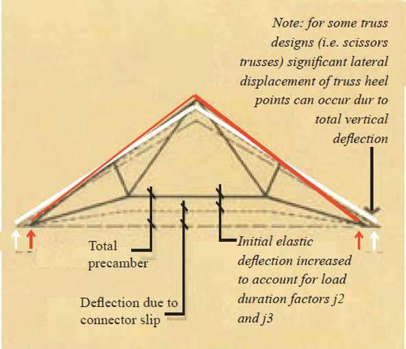
Architectural trusses always warrant calculation of deflection and it's an important consideration when assessing visual aspects such as straight lower chords or where excessive movements may cause distress to other building elements. Calculations should consider creep deflection (load duration factors J2 and J3) as well as slip of the connections. These are most easily developed with the aid of computer programs that incorporate the effects of fastener slip. Click on the figure below to see an exaggerated distortion that illustrates the components of truss deflection. Critical members can be pre-cambered where dead load deflections are significant. To ensure a member remains straight after the long term application of load, the lower chord (and sometimes the upper chord) can be bent upward at each internal node during fabrication.
Criteria Level: 2.03
The member sizes, connector clearances and web inclinations will all contribute to the uniqueness of the truss so it is usually necessary for working drawings of architectural trusses to be to a high level of detail. The smallest alterations can make the most significant impact on nodes and for this reason, nodes need to be drawn to scale to assess the practicality of each design.
Refer to AS1100 part 501 Structural Engineering Drawing for drafting techniques for structural timber detailing. Some of these techniques are also illustrated below.
Criteria Level: 2.04
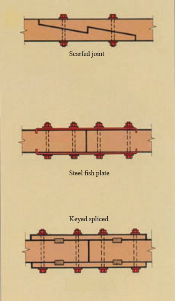
The truss span, chord arrangement and available timber lengths dictate the need to splice. This is more commonly required in the bottom chord as the pitched top chord is effectively spliced at the apex. From a structural perspective the splice can be easily designed, however it can prove problematic from a visual perspective, especially if it is placed asymmetrically. Where significant aesthetic issues arise, the use of a glue-laminated beam, eliminates the need to splice.
Where splicing is necessary, the location should be chosen to minimise its visual impact. If the chord is in compression it should be spliced at the node where lateral restraint is provided. If in tension it is often located at about 20% of the inter nodal length to minimise deflection due to self weight.
Criteria Level: 2.05
The open nature of architectural trusses precludes the use of usual ceiling systems to hold the lower truss chord in line.
Accordingly, lower chord restraint options include:
- Placing the lower chord on its flat
- Placing a beam on the flat and forming a T-Beam with the bottom chord
- Introducing a system of timber or tubular binders to work with the services
- Using unobtrusive tie rods or cable to brace the nodes back to a stable element
- Designing the lower chord as a very wide spaced column that can carry the buckling load over its full length
- Altering the roof pitch or roof mass so that the uplift is minimised
- Using bracing sets between adjacent trusses only
- Using fly bracing from ceiling line to lower chord
Criteria Level: 2.06
It is a typical feature of architectural trusses for the support points to be exposed. As they are spaced significant distances apart, the forces transmitted can be substantial and conventional tie-down using hoop iron or framing anchors are usually inadequate. The figure below illustrates some typical hold down connections.
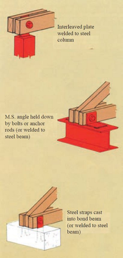
Girder truss brackets produced for toothed plated trusses can provide a useful hold down. In other cases, specially fabricated steelwork may be necessary to transmit and uplift lateral forces into the supports.
Criteria Level: 2.07
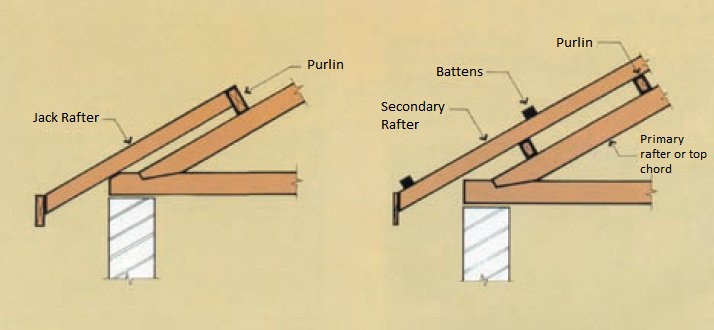
Setting purlins above the top chord is generally the easiest method of design. Where the top chord is paired the webs can penetrate the ceiling level to provide fixing to the purlins. For purlins not at nodes a simple block can project above the ceiling line while doubling as blocking for the spaced top chord.
If the spacing of the purlins means they cannot provide sufficient support to the lining, ceiling battens will be necessary. For purlins located above the upper chord, the battens are fixed underneath. An advantage of this method is that it allows concealed framing anchors to be used for purlin tie-down. In these cases, the top chord may be over-sized to compensate for any visual diminishment caused by the thickness of the batten and ceiling.
In some applications, a secondary rafter (taking all the bending) may be set above the top chord. The purlins may then be placed in line with the rafter. The tops of the purlins can be set level with the upper chord, allowing concealment of joins within the ceiling material.
Joist hangers or similar provide a suitable means of connection; exposed purlins can also support secondary rafters. For roofs on a slope greater than 20°, the roof and ceiling weight acting down the slope becomes a significant consideration. In these instances the purlins have to be designed for bi-axial bending or alternatively, these forces resisted by bracing.
Criteria Level: 3
The following section outlines the key points to address in preparing the designed and specified architectural truss for assembly and installation.
Criteria Level: 3.01
The high standard of workmanship required for these finely detailed frameworks is usually only achieved with factory fabrication. With jigs and templates the necessary precision can be achieved, thus eliminating the need to rematch components on site. Trial assembly off site, for more complex roof structures, may be beneficial in confirming the accuracy of the fabrication.
For applications utilising unseasoned hardwoods, extra attention of the following is required:
- Moisture content should preferably be less than 25% at fabrication
- Wax emulsion sealers should be used on the cut timber ends so that rapid moisture loss is minimised, reducing the probability of end splitting. (Ensure any selected sealant will not interfere with the planned finishing)
- Bolt holes should be drilled 10% oversize and bolts, shear plates and split rings should be well greased.
Take care in preserving connector spacings, along with end and edge distances as required by AS1720 Timber Structures Part 1: Design Methods. Connection design strengths, in accordance with AS1720, require fasteners to not be located in sections of timber containing visible strength reducing characteristics such as knots. This is easily complied with in reconstituted timber, but can be problematic in knotty timbers and those with defects such as gum pockets and shakes. Accordingly, the node positions in timber connections needs to be carefully checked before timber is cut, so that the design assumptions can be checked for compliance and timber waste minimised.
It is advisable for trusses to be assembled on the flat and the hog in the precambered chords maintained until all fasteners are installed. Once split-rings and shear-plates are installed they are difficult to detect, so a thorough inspection will be necessary.
Prior to assembly the timber should receive a preliminary application of the intended finish and to facilitate future cleaning all exposed edges should be arrised. Depending on site conditions, final finishing can be done on site or in the factory.
Criteria Level: 3.02
During transportation, trusses should be fully supported in either a horizontal or vertical position. Care is required whilst tying down to avoid any undue stress on the chords or webs.
Architectural trusses are often best displayed in roofs pitched at 30°. With limitation on transport heights, a pitched truss of 12m span or more will require disassembly for transport. When this is necessary, the construction tolerances require that members be tagged and marked so that components across adjacent trusses are not mixed during reassembly.
Traditional trusses have generous arrises on exposed edges and retaining this feature can also reduce damage to trusses during handling. In addition, the finish to the truss should be protected during transportation with either a water repellent, priming or protective wrapping.
Criteria Level: 3.03
Timber trusses should be stored on the site flat and clear off the ground. Once installed they should not be left exposed to weather for any extended period. Repeated wetting and drying can cause damage to the strength of the timber. Where a protective covering is necessary, ensure free air circulation is allowed around the trusses.
The recommended lifting method will depend on factors such as truss length and shape. In general, the truss sling should be located at equal distance from the truss centreline and be approximately one third to one half a truss length apart. The angle between sling legs should be 60° or less and where truss spans are greater than 9000mm spreader bars with attachment to the panel points should be used. Never lift a truss by the apex joint only. Trusses may also be placed on the top plates by pulling them up on skids, spread at 3000mm.
Criteria Level: 3.04
It is important to ensure any supporting structures are level and square. Confirm that the load bearing top plates are level and straight in length, that the structure is of the correct dimension and that the internal walls are correctly set below the outer wall level.
Criteria Level: 3.05
When site assembly is required, a level working surface is essential. Supporting packing should be placed at each node and the connected components, making sure that the precamber is achieved. Use podgers to line up bolt holes, rather than the bolts themselves. Ensure that all the special connectors and washers are installed before the truss is tightened. Install bolts to simplify the tightening of nuts, particularly when working with unseasoned timber.
Criteria Level: 1
Utilise fabric or rope slings when handling trusses to protect the timber and minimise damage. It can be useful to mark the truss position on the wall plates before lifting the truss. In most cases when lifting, these trusses are strong enough not to require lateral bracing but once in position, temporary bracing is recommended to prevent overturning.
Criteria Level: 1
Possible finishes to the timber truss include typical waxes, clear polyurethanes, stains and opaque paints. Many applications specify for a natural sawn or dressed finish. Refer to the WoodSolutions resource on Exterior Timber Finishes for more information on timber finishing options.
Criteria Level: 1
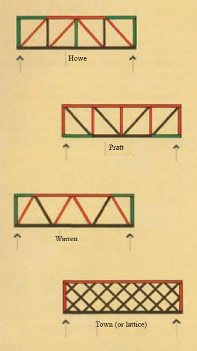
The overall design of an architectural truss is most influenced by the specific design of compression and tension members. Compression members are primarily concerned with achieving the highest resistance to buckling and tension members to achieving connector end distance.
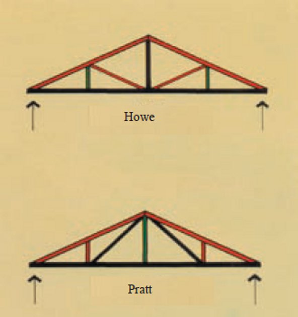
The figures contained within this section provide some detail to the internal loadings. Truss members are colour coded to indicate the type of forces resulting in the members due to the weight of the roofing and ceiling.
- Black indicates tension
- Red indicates compression
- Green indicates very little load in a web used for restraint of the lower chord
Contemporary timber construction practice dictates that architectural truss design should not carry the roof loading to the node but rather, the purlins and ceiling joists load the top chord directly. Consequently the top chords carry a bending load as well as the axial load.
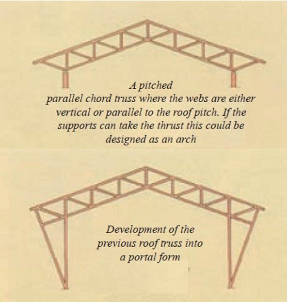
The following figure demonstrates the possibilities for a pitched roof with a horizontal lower chord.
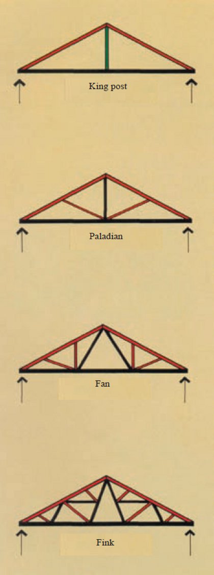
And the following figure demonstrates the development of a simple pitched roof. As webs are added the bending stress to the top chord is reduced causing the possibility of a reduced top chord size, increased truss spacing or increased spanning capability.
Traditional trussed roofs have steep pitches. The design style originates from the northern hemisphere where shedding snow was a key objective. Steepening the roof pitch, increases the depth of the truss and this in turn reduces the loadings on the truss members and connections.
Guide limits for maximum spans are difficult as there are so many variations in truss design. In some applications a heavy membered truss has a better appearance for a given structure, while in others a finer framework may be more appropriate.
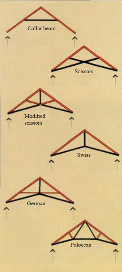
Trusses with raised lower chords heighten their expanse, creating a feeling of spaciousness. A minor disadvantage is that such trusses will require stronger members and connections compared to some others. The following figure illustrates the evolution of the ‘Polonceau' truss from the simpler ‘Collar Beam' truss. When these scissor type trusses are loaded, the support points tend to move apart horizontally and this should be considered during design.
Pitched roof lines can also be achieved using parallel sided trusses. Note that a field splice at the apex will usually be necessary for transportation. Parallel chord trusses are extremely versatile and can be utilized to support floors in mezzanine construction or as girder trusses carrying pitched trusses or rafters.
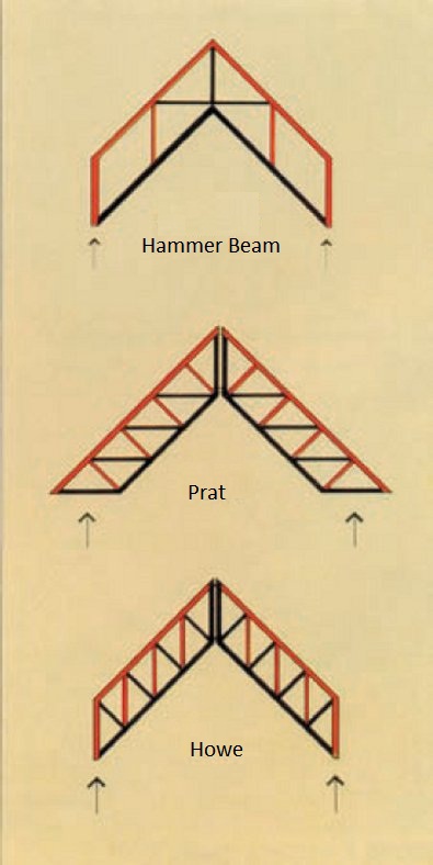
The following figure demonstrates parallel sided trusses suitability for flat roof construction. A slight pitch may be introduced on the top chord or on both. Alternatively graded purlins may be used to achieve fall to the roofing.
All the truss shapes discussed can be combined together, tilted or inverted to meet the application requirements. Note that where wind suction acts on a roof the lower chord of a supporting truss changes from tension to compression and in these cases buckling can become a problem. Other situations that lend themselves to this problem are low-pitched roofs and lightweight roof-ceiling systems. Remember that the designer has some influence over the roof dead load and pitch. In addition bracing can stabilise members subject to high wind speeds.
Criteria Level: 2
The size of timber used for architectural trusses is typically:
• 150mm deep for chords
• 100mm deep for webs
• 75mm (minimum) thick for single member trusses
Standard requirements will usually include large section sizes (200x100mm), long lengths to reduce unattractive splices and clear timber in node locations.
Unseasoned hardwood can be a suitable material choice. Moisture content is an important consideration, and care should be exercised in detailing to allow shrinkage movement to occur as members dry out. Fabrication should not be commenced until the moisture content has dropped below 25%. Shrinkage can cause movement of one member away from another at the joints, which can be aesthetically displeasing. A solution to this is to use a different joint detail, glue-laminated hardwood or seasoned hardwood in a multi-member system.
There are many obvious benefits to using sawn timber for truss members, particularly where connections are made using gussets and side plates. The combination of timber and steel materials can produce a variety of visually pleasing truss designs and styles.
Glue laminated timber is an ideal truss material, particularly in cases where the truss shape needs chord continuity at the nodes for stability and thus requires longer length chords. In addition, being seasoned and available in higher joint strengths, the node connection detail is generally more compact.
Laminated veneer lumber LVL is available in large depths but limited to 63mm widths. If buckling presents a problem, compression elements can be made up of multiple members. For an extremely economic joint design, steel connection plates at nodes can be interleaved between the members. The appearance of irregular glued scarfed joints in LVL may restrict its use to painted trusses.
Softwood is another ideal material for architectural trusses as it has high versatility and workability, combined with a lightness that enables large sections to be easily manhandled. Unseasoned softwood offers the advantage of low shrinkage during fabrication, while seasoned softwood has the advantage of increased joint strength and enhanced stability. As it is most commonly available in 45mm maximum thickness, seasoned softwood needs to be used in a multimember form.