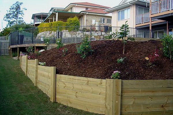


The natural appeal, strength and versatility of timber makes it an ideal choice for retaining wall landscaping applications.
Retaining wall systems include cantilevered round or sawn timber, mass wall and crib wall construction. Walls up to one metre in height follow a basic design and can usually be constructed using standard proprietary wall systems. An engineer will be required to plan and design walls greater than one metre, including the footings and drainage.
Drainage of retaining walls is a critical factor in influencing the long term stability of the wall and should thus form a significant part of the design and planning process.
Regular care and maintenance of retaining walls is essential in ensuring the long-term stability and safety of the structure.
Criteria Level: 1
Answering both function and aesthetics, timber with its natural look and in built versatility, is the ideal and often preferred material for outdoor applications.
Sawn timbers are a popular choice in retaining wall construction and for in ground contact are usually unseasoned, treated or naturally durable. There is more flexibility for those used in above ground environments, with seasoned sawn timber also an option. Timbers that support structural loads are required to be stress graded to AS 2082. The minimum stress grade for sawn timber should be F7 for softwood and F14 for hardwood.
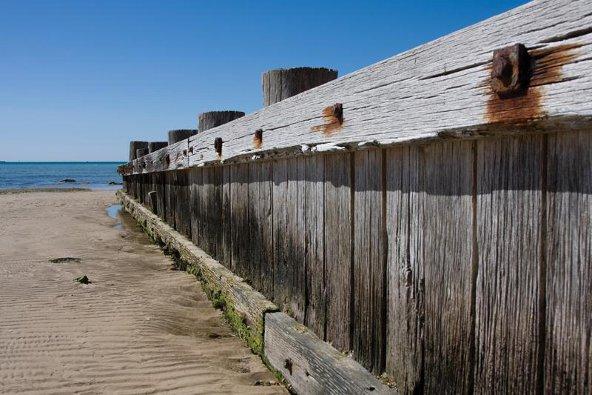
When specifying for durability consider that a retaining wall will likely form part of a landscape where plants, grass and shrubs are grown and this will in turn significantly increase the risk of insect and fungal attack. In these instances, durability class 1 timber species or timber preservative treated to H5 is recommended. The heartwood of naturally durable species that are suited to retaining walls include grey gum, tallowwood ironbark and forest red gum, these species are also termite resistant in accordance with AS 3660.1. Provided that the sapwood of the log is removed, or alternatively preservative treated to H5, these timbers will perform well for over 25 years.
It should be noted that H5 treated softwoods have an expected service life of 50 years or more. Their wide sapwood band can be made highly durable with CCA preservative treatment in accordance with AS 1604.1.
Criteria Level: 2
Mass Walls: Mass walls are only suitable for low walls as they rely on a mass of timber to resist the contained load. The wall is typically formed by sleepers spiked together in a staggered pattern.
Timber Crib Walls: Crib walls are a common form of retaining wall, generally comprised of small pieces of treated hardwood placed in parallel rows and connected at regular intervals. Free draining granular fill is packed around each layer of the crib, creating a strong mass of stable earth.
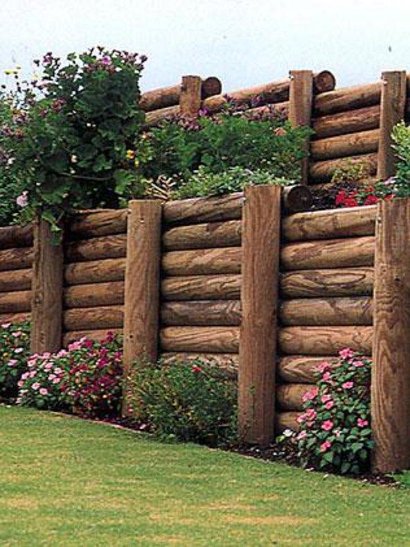
Cantilevered Walls: Cantilevered walls are well suited to large scale engineered designed retaining walls. They are usually constructed with round or sawn timbers, with a third of their length buried into the ground and cantilevered out to support timber walling. These poles are set at close centres to support the timber that spans between them.
Criteria Level: 1
The following points should be addressed as part of the site assessment process. In most instances consultation with a geotechnical engineer will be necessary.
- Retaining walls constructed on sloping sites require extra consideration as full ground support cannot be relied upon. In most cases larger posts with additional embedment will be required. For slopes steeper than 10° a geotechnical engineer should be consulted.
- The horizontal force generated by the vertical load of permanent structures such as buildings, swimming pools and roads can have significant impact on the performance of retaining structures. In these instances a geotechnical engineer should be consulted. (Lightweight fencing is not a concern).
- Terraced retaining walls require specific design by geotechnical engineers as the weight of a more elevated retaining structure will apply additional loads to the structure below. The need for engineering consultation includes those instances where a new retaining wall is constructed above or below an existing wall.
- Retaining walls that are to be constructed in proximity to service locations should be referred to local authorities. Many authorities have specific requirements for constructions such as these, usually in relation to minimum clearances so that walls impart no load on the services.
- Drainage of both the wall area and the surrounding environment must be assessed. Investigations should confirm local groundwater levels and the possibility of seepage or surface run off. Inadequate drainage can result in overloading of the wall and scouring of the footings, either of which may lead to wall failure. Good drainage behind and/or through the wall is therefore essential in ensuring a long lasting, safe and sound retaining wall structure.
- While it is vital that the entire wall is strong enough to support its load, it is the foundations below the ground that are critical in sustaining the structure. Regardless of the strength of the upper section of the wall, if foundations are weak there is little, if anything, to stop the wall from collapsing under pressure. Recommended foundation materials include stiff clay, weathered rock and dense sand or gravel. Recommended backfill materials include sand, sandy gravel and gravel.
Criteria Level: 2
Outlined below are the key structural components that require consideration for every retaining wall design.
Criteria Level: 2.01
The vertical load of the soil and anything that rests above, generates a horizontal force that the wall must withstand. In addition to the load the wall will initially bear, any potential future increases must be accounted for during the design stage. This includes permanent loads and temporary loads such as heavy vehicles.
Criteria Level: 2.02
Normal gravitational forces cause the backfill to slide towards the wall. As this occurs it develops frictional forces on the sliding surface, which significantly reduces the load to be resisted by the wall. This can cause the retaining structure to be made lighter. For the wall to generate its own internal friction it must move before the backfill. This is achieved by erecting the wall with a batter so that when it rotates the pressure on the wall causes it to straighten.
Criteria Level: 2.03
To aid dissipation and avoid the build up of groundwater to the load carried by the structure, a vertical layer of free draining material must be placed immediately behind the wall. This layer will reduce the likelihood of fine material being carried through the wall by water. In addition, where the surface of the backfill drains towards the wall, a surface drain should be provided to prevent water spilling over the wall into the drainage material.
Please note that wherever a cut is made the moisture of the retained soil will reduce, in particular, shrinkage will occur in reactive soils. A geotechnical engineer should be consulted if a building is nearby, as uneven settlement may occur.
Criteria Level: 2.04
The rear of the wall is filled with a material called backfill typically made up of sand and/or gravel. The nature of the material determines the magnitude of the load to be carried up the wall. Typically, the more free-draining the backfill, the less load is exerted. Sand and gravel are compacted with a minimum of effort and consequently there will be little to no settlement later. The top 200mm of backfill may be garden soil.
Criteria Level: 1
The following provides an overview of the steps involved in the construction of a typical retaining wall.
- First, the length and height of the wall should be measured out and then a stake driven into the ground of both ends of the wall, with a string line running from one stake to the other. Mark out the location of the posts by dividing the total distance into equal sections.
- The required depth of the holes should be bored into firm natural ground. Dig 300mm diameter holes for posts of 150mm. (Dig 450mm diameter holes if posts are larger). Angle the borer to allow for the slope of the poles (1:10). Place approximately 100mm of gravel layer into the holes and then place the two end posts in place to designated batter and align the backs to achieve the best line. Concrete back fill is adequate for treated softwood posts. For hardwood posts, which have a much smaller treatment zone, backfill with no fines concrete that is ready mixed (or hand mixed manufactured to AS1379) is recommended. Place the concrete in and around the posts to within 50mm of the ground level.
- To set up intermediate posts, a string line should be run between the end posts at the top and bottom. Place bracing behind the posts and temporarily attach this, while concreting the posts in place.
- When the concrete has set, ensure the tops of the posts are level and straight and measure down on each post to pinpoint the top of the bottom rail. Starting from the bottom, place the rail in position and commence attaching it to the back of the posts. Ensuring they are level, fix one hot dipped galvanised nail to each post. Stagger the end joints so that the butt joints occur on alternate posts.
- Lastly, a trench should be dug against the corner of the bottom of the wall for 50mm deep of drainage sheeting to be laid. Lay the drain pipe on top of the sheeting with a slight fall to one end of the wall. If possible allow open access to the drain from both ends to allow for flushing out. Cover the drain pipe with 250mm of free-drainage gravel and encase with a geotextile screening fabric. The gap between the wall and the bank can now be filled with well compacted back fill up to 100mm below the top of the wall. The top 100mm can be filled with top soil for plant growth.
Criteria Level: 1
To ensure ongoing structural stability and safety, regular monitoring of retaining walls is essential. Monitoring should include regular visual inspections, specific inspections after weather events like heavy rainfall and basic monitoring of lateral deflection. A thorough visual inspection should detect any cracks or ruptures, excessive movement, drainage issues and physical or environmental changes, all of which should be attended to immediately.